COMPRESSIBILITY EFFECTS – DELTA WINGS
As previously noted delta wings are primarily used on aircraft operating at Mach numbers above 1.0. At these conditions their performance is superior to other configurations with the result of their selection for many high speed aircraft, including the supersonic transport types. The variable swept wing can be thought of as a delta type when in the fully swept configuration and thus can be included as the one best type for operation at M 1.
Subsonic Compressibility Effects. The performance of delta wings given previously in this chapter is for conditions where compressibility effects are zero, M = 0. The effect of increased Mach number is shown in figure 31 and shows an increase in both the slope of the lift curve and lift drag ratio, which peaks at M =: 1. The variation of the lift curve slope with M is due to compressibility and can be accounted by the Prandtl Glauert transformation such as described in Chapter VII. With this correction the potential lift represented by Kp is increased by compressibility to a greater extent than the vortex lift correction К v. To find Kp Ду the aspect ratio is corrected by the equation
A’ = A /l-M2 (10)
where A’ is the aspect ratio used to read К p and К у on figures 9 and 10, and M is the free stream Mach number. The К factors must also be corrected thus
Kpc =Kp / / 1-м2 (11)
Kvc =KV fM (12)
fM = Vх! + tan2W //3 + tan2A (13)
Comparison of the variation of the lift curve slope calculated with equations (11) and (12) with that measured in figure 31 indicates good agreement.
|
|
|
|


 |
![COMPRESSIBILITY EFFECTS - DELTA WINGS Подпись: and Ky = Tf[(16-(A/3 )Z)(A2 + 16)/Z/16E2 (15) where E = elliptic integral of the second kind where modules = [1 ~( cotAT p )2]/2. In this case /3 = /мї - 1. In (12,d) comparisons of the calculated results of equations (14) and (15) with test data indicate good agreement.](/img/3130/image1243_1.gif) |
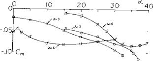
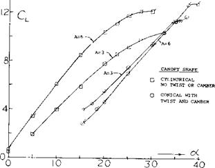
Figure 33. Lifting and moment characteristics of two-lobed parawings, A = 3 and 6.


