Directional Stability and Control in Ground Rolls
The modern light plane tricycle landing gear has main wheels behind the center of gravity and a steerable castering, or freely swivelling, nose wheel ahead of the center of gravity. This arrangement, invented and applied by Fred C. Weick (1936), put an end to the ground loop. The ground loop is a rapid yaw from the runway heading and a swerve off the runway. It is a problem for tail wheel landing gears, which were still used by some designers for many years after Weick’s invention.
|
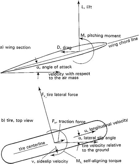
Figure 14.8 Forces and moments acting in wing sections and rolling tires. (a) Wing section. (b) Tire, top view. (From Abzug, 1999). |
Figure 14.9 Ground roll eigenvalues for Cessna 182 at 3 airspeeds. (From Abzug, 1999)
The physical mechanism by which the main wheels of a tricycle landing gear create yaw stability during ground roll is explained in Weick’s 1936 paper. However, it is possible to model mathematically the landing rollout process in the same way we model flight dynamics (Abzug, 1999). The model produces either eigenvalues or roots for ground rollout small perturbations or nonlinear equations suitable for 6-degree-of-freedom transient analysis.
The keys to mathematical modeling of ground rolls are models for the forces and moments applied to the airframe by tires in contact with the ground and for landing gear oleo struts. Both are available in the literature from automotive and aviation research. There is an interesting analogy between the forces and moments acting on wing sections and on rolling tires, as shown in Figure 14.8. Tire lateral force exhibits a linear relationship, up to a stall, with tire lateral slip angle, a sort of tire lift curve. Tire lift curve slope with slip angle is used to generate tire stability derivatives, which are added to the normal airplane small-perturbation equations of motion to produce eigenvalues in ground roll. Figure 14.9 has calculated eigenvalues for a Cessna 182 rollout at three airspeeds, as functions of main gear longitudinal distance from the center of gravity. Positive eigenvalues, indicating directional instability, occur for main gear locations just ahead of the center of gravity.
Linearized ground roll analysis can be applied to large airplanes with complex wheel arrangements and power-steered nose wheels, with less assurance of meaningful results. In those cases, linearized analysis may show ground handling trends, but one should plan
on full nonlinear 6-degree-of-freedom analysis, including tire forces. An extended analysis and simulation of ground roll was made for the Navy/Boeing T-45 trainer by the NASA Langley Research Center (Chambers, 2000). With proper tire dynamic models and inclusion of aircraft roll attitude, a pilot-induced yaw oscillation was reproduced.


