HIGH LIFT AND CONTROL DEVICES
The application of flaps to obtain high lift and control for delta wings requires consideration of the differences in flow produced as a result of the leading-edge vortex. As discussed earlier in this chapter, the leading-edge vortex increases the lift which is non-linear with respect to the angle of attack. Further, the flow produced as a result of the vortex changes the pressure distribution on the wing, so that it might be expected that the effect on lift of a flap deflected into the vortex would be different than if deflected away from the vortex. Since the vortex is influenced by the shape of the leading edge, the effectiveness of flaps will be different for wings with different types of cross sections.
There are many different types of flaps that can be installed on delta wings, such as plain, split and slotted types. Because of the limited span it is generally necessary to use these flaps to obtain high lift and control ;.n pitch and roll. Such flaps are called elevons.
M :r 87.7
|
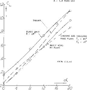
WING BODY COMBINATION WITH PLAIN FLAPS AND LEADING EDGE FLAP A = 2.1 TIPS ON |
|
Figure 27. Delta wing body combination with plain flaps. |
Plain Flaps. The characteristics of plain rectangular flaps attached to the trailing edge of a round leading-edge delta wing are shown on figure 3, Chapter IX. On the basis of flap area to total wing area, the effectiveness of the flaps would be predicted from figure 2 of Chapter IX which was developed from test of flaps on straight wings. The use of flap area to wing area to predict the effectiveness is further confirmed by tests of a large model delta wing in the 40 x 80 foot wind tunnel (13,a). A delta wing with sharp leading edges and a plain type of flap and a fuselage was tested, figure 27.
Flap Effectiveness = (dCL /dot) / (dCL /d6 ) (6)
is close to that predicted for this type of flap on figure 2 of Chapter IX. Although the wing tested has sharp leading edges, a comparison of the lift with the theoretical prediction indicated the slope of the lift curve is low. The low lift curve slope does not appear to change the flap effectiveness and is probably caused by the central body.
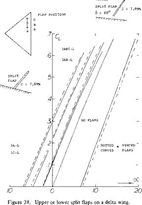
Split Flaps. Tests of 60c split flaps on a delta wing with an aspect ratio of 3.03 are given on figure 28. These tests (13 ,b) were done in conjunction with spoiler flaps of the same size to be used together as dive breaks or separately for increasing lift. The flaps were tested at various chordwise locations on the wing for different length spans and flap chords. The split flaps were also tested in the vented and non-vented configurations as indicated on figure 28.
Based on equation 1 of Chapter V the flap effectiveness can be measured in terms of (C^ /C)n for flaps on rectangular wings. For such wings with the same type of section test in conjunction with the above data, the data of (13,b) indicates n would be 1.03. As above, the flap effectiveness ratio is found in terms of the area ratio. This indicates for delta wings with split flaps the effectiveness is
dS/dct’ = (Sf/S)’93 (7)
The test data of (13,b) also indicated that if the flap is vented the n would increase. Further, the inboard flaps are more effective than those outboard when located toward the trailing edge of the wing.
The effect of deflecting split flaps located on the upper surface of the wing is given on figure 27. The effectiveness for decreasing lift is the same order of magnitude as for increasing lift with the flaps located on the lower surfaces of the wing, speed breaks are obtained without changing the basic lift slope of the wing.
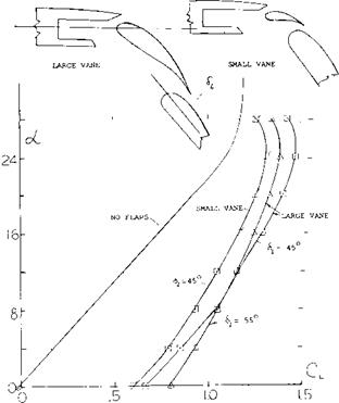
Double Slotted Flaps. Because of the high angle of attack needed for landing with delta wing aircraft and the low span, double slotted flaps have been investigated (13,d, e). Typical results are presented on figure 29 for a wing body configuration with double slotted flaps extending to the.666 spanwise station. The flaps were investigated with a large and a small intermediate foil. Up to flap angles of 45 ° both configurations had nearly the same performance at zero angle of attack. This performance improves
|
VtrNTTvD
|
with flap angle for the configuration with the larger foil for Да: =* 6° . Above this angle the payoff in
ACl_ is reduced with flap angle until at Cux the 6$ = 45u is best. It is observed that the wing with Sf = 45° has the same lift curve as the basic
configuration up to the stall angle.
For the wing with the double slotted flap with an adequate intermediate foil the flap effectiveness can be predicted based on the flap type, area ratio and the deflection angle, using data such as given in Chapter V. It therefore appears that the performance of flaps on delta wings can be predicted with good accuracy based on the characteristics of the flaps determined on straight wings.
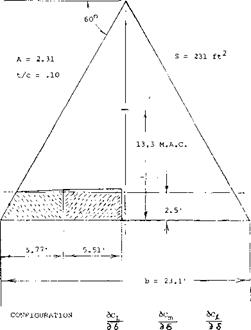
Part Span Flaps. Tests (13,c) were of part span flaps on one side of a delta wing, figure 30, to find the effectiveness as a function of spanwise location. From the data given it can be concluded that the effect of the location of the flap spanwise is of secondary importance and the lifting effectiveness is proportional to the span fraction. Regardless of flap-span fraction, use the value of b/c as the aspect ratio responsible for the flap lift curve slope. For the configuration in figure 30 that ratio is Af = b/cf = 9, and the “lift angle” is
dot /dC(_ =11 + 20/9 = 13.2° (8)
so that dCL I dot = 0.076. The fraction of the ‘‘half”
span flap is actually 0.9/2 = 0.45. The lift due to flap deflection may thus be
dC^b /d6 = 0.076(Sf/b2) = 0.076(0.45)/A (9)
The result of 0.0038 is somewhat larger than the tested value (0.0081/2.31 = 0.0035).
Aileron. The half and/or part-span trailing-edge flaps of the delta wing in figure 31 can conveniently be used as ailerons. Of course, in regard to their moment about the longitudinal axis, there is a difference between outboard and inboard flaps. The roll-moment contributions listed in the illustration yeild arms “y” as follows: outboard and inboard flaps. The roll-moment contributions listed in the illustration yeild arms “y” as follows:
y/b = 0.0004/0.0045 = 0.1; (0.12)
= 0.0012/0.0040 = 0.3; (0.33)
= 0.0016/0.0081 = 0.2; (0.25)
For comparison, the purely geometrical ratios are added in parentheses. Tentatively, therefore, the moment arms may be considered to be between 0.8 and 0.9 of the geometrical ones.
In examining the rolling moments as determined from test, the difference between positive and negative aileron deflection is small at the lower angles of attack. Further, no significant changes are noted between wings with round or sharp leading edges. This indicates that the leading-edge vortex does not influence the results in this range.
|
Figure 29. Double slotted flaps on delta wing airplane. |
Antisymmetric Deflection. In a conventional, more or less straight wing (with higher aspect ratio) the antisymmetric deflection of the ailerons produces lift differentials in each wing panel corresponding to a lift curve slope based upon Vi the wing’s aspect ratio. Based on the results of (13,c) the use of up and down ailerons will double the rolling moment shown on figure 30, determined for one side of the wing. At the lower angles of attack the yawing moment is negative with up or down flap deflection switching at angles above 10 degrees. This change will effect the flying qualities of the aircraft thus requiring special design consideration.
V
|
|
|
INBOARD ELEVONS OUTBOARD ELEVONS BOTH ELEVONS |
|
.0045 о 0041 о 0081 |
|
.0020 о 00’20 .0038 |
|
.0004 .0012 .0016 |
Figure 30. Part span flaps on a large delta wing.
(14) Parawings:
a) Rogallo, Flexible Wings for Transportation.
b) Sleeman, Parawing Aerodynamics, A&A Engineering, June 1963.
c) Mendenhall, Aero Characteristics of Two-lobed Parawings, NASA CR-1166 and J of А/С, Nov, Dec 1968.
d) 

 Polhamus, Experimental and Theoretical Studies of Parawings A = 3 and 6, NASA TND-972.


