Low-Drag Considerations
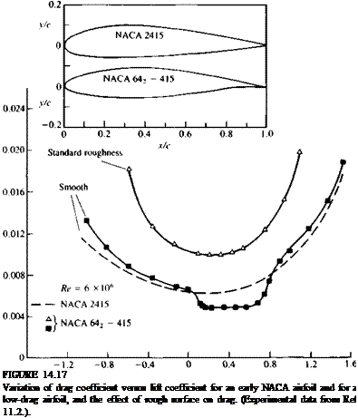
When low drag of the lifting surface is sought (e. g., for an airplane cruise configuration) then, as mentioned, large laminar boundary layer regions are desirable. In order to maintain a laminar boundary layer on an airfoil’s surface it must be as smooth as possible and also a favorable pressure gradient can delay the transition to a turbulent boundary layer (Ref. 14.8, pp. 363-364). A favorable (negative) pressure gradient occurs when the pressure is decreasing from the leading edge toward the trailing edge (thus adding momentum) and can be achieved by having a gradually increasing thickness distribution of the airfoil. This is demonstrated in the inset to Fig. 14.17, where an earlier NACA
C,
 |
2415 airfoil is compared with a NACA 642-415 low-drag airfoil. The inset to the figure clearly shows that the maximum thickness of the low-drag airfoil is moved to the 40% chord area, which is further downstream than the location of the maximum thickness for the NACA 2415 airfoil. The effect of this design on the drag performance is clearly indicated by the comparison between the drag-versus-lift plots of the two airfoils (at the same Reynolds number). In the case of the low-drag airfoil, a bucket-shaped low-drag area is shown that is a result of the large laminar flow regions. However, when the angle of attack is increased (resulting in larger C,) the boundary layer becomes turbulent and this advantage disappears. For comparison, the drag of a NACA 642-415 airfoil with a standard roughness112 is shown where the boundary layer is fully turbulent and hence its drag is considerably higher.
A large number of airfoil shapes together with their experimental
validation are provided in Ref. 11.2 (e. g., for the 6-series airfoils of Fig. 14.17 on pp. 119-123). Also, the airfoil shape numbering system is explained there in detail. For example, for the 642-415 airfoil the last two digits indicate the airfoil thickness (15%). The first digit (6) is the airfoil series designation and the second digit indicates the chordwise position of minimum low pressure in tenths of chord (or the intention to have about 40% laminar flow). As long as the boundary layer stays laminar in the front of the airfoil, its drag is low (see the bucket shape in Fig. 14.17) and the range of this bucket in terms of AC, is ±0.2 near the designed C, of 0.4 (hence the subscript 2, and the digit 4 after the dash).
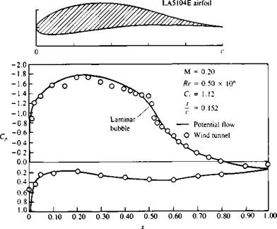
Most airplane-related airfoils operate with a Reynolds number larger then 106, but when the Reynolds number is below this number (as occurs in small-scale testing in wind tunnels, or low-speed gliders and airplanes, etc.) then it is possible to maintain large regions of laminar flow over the airfoil. This condition is more sensitive to stall and usually a larger laminar bubble exists. The effect of such a laminar bubble on the airfoil’s pressure distribution is shown in Fig. 14.18, where the plateau caused by the laminar bubble is clearly visible (see also Fig. 14.16). For further details about low Reynolds number airfoils the reader is referred to a review article on this topic by Lissaman.1412
|
c FIGURE 14.18 Signature of the laminar bubble on the pressure distribution of an airfoil. (Courtesy of Douglas Aircraft Co. and Robert Liebeck) |


