MAIN ROTOR OPERATION IN FORWARD FLIGHT
§ 19. Characteristics of Main Rotor Operation in Forward Flight
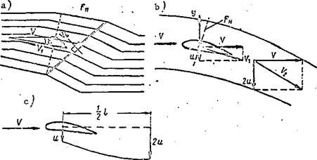
We recall that the term forward flight refers to operation of the main rotor in an undisturbed stream which approaches the rotor nonparallel to the hub axis (see Figure 12c). While in the axial flow case, the rotor imparts to the air mass traveling along the axis additional momentum in the same direction, in the case of forward flight the rotor also imparts to a definite air mass some additional momentum, only this time not in the direction of the undisturbed approaching stream, rather in the direction along the rotor axis, downward. This leads to the appearance of the so-called downwash (Figure 27a).
The downwash magnitude is connected directly with the magnitude of the thrust which the main rotor develops in the forward flight regime.
In accordance with wing and propeller vortex theory, developed by Zhukovskiy in the 1905-1921 period, the wing lift and the main rotor thrust in the forward flight regime can be determined using the same formulas.
We imagine a stream of circular cross section, flowing past a wing (Figure 27b). The stream approaches the wing with the velocity V. As a result of the formation of the induced vortices, the wing imparts to the air /40 mass per second mg the vertical velocity u, termed the induced velocity.
Vortex theory shows and experimental aerodynamics confirms that there is a gradual increase of the induced velocity behind the wing.
|
At a distance equal to about 0.5Z (wing half-span) the induced velocity
reaches the value 2u (Figure 27c). Thus, the air acquires from the wing
additional momentum equal to m 2u.
s
The energy conservation law states that the momentum increase equals the impulse of the force. The impulse of the force per second will be simply the wing lift. Consequently,
Y — tns2a. (із)
Let us find the magnitude of the air mass flowrate mg. The stream section area F^, normal to the vector V^, equals the area of a circle of diameter equal to the wingspan l.
The velocity vector Yx=s]/ ц (V is the undisturbed flow velocity, and u is the induced velocity). Then
Substituting this value of the mass flowrate into (13), we obtain
![]() Y=2?FnV1u.
Y=2?FnV1u.
Thus, the wing lift depends on the air density, wingspan, flight speed, and the induced velocity with which the wing deflects the stream downward.
From (15) we find the magnitude of the induced velocity /41
Г
U~ 2PFnVx ‘
Since the stream induced downwash angle is small, we can assume that
The downwash formed by the main rotor (see Figure 27a) is similar to the downwash due to a wing with span Ъ = D.
The air approaches the rotor with the velocity V and is deflected downward as a result of the induced inflow velocity V^. The resultant rotor velocity will be equal to the vector sum of the velocities of the undisturbed stream and the induced velocity
Vi^V + Vf.
The angle є between the vectors V and is the induced downwash.
Continuing the comparison with the airplane wing, we can say that the air mass flowrate ftls — pFiiV і passes through the area F normal to the resultant velocity vector Vl:. Since the rotor is taken to be a wing with span Ї = D, then
л-
i. ![]() e., the area perpendicular to the vector Vi,. will be equal to the area swept by the main rotor = F.
e., the area perpendicular to the vector Vi,. will be equal to the area swept by the main rotor = F.
In the forward flight regime the downwash velocity is also equal to twice the inflow velocity. On this basis and using ideal rotor momentum theory, we find the thrust in the forward flight regime using (4)
T = m V, = m 2V.. s dw s x
Using (14), we can write
If F„ = F, then N
T = tyFViV,.
If we account for tip and root losses, this formula can be written in the form
T= 2xpFVxVt.
Consequently, main rotor thrust in the forward flight regime depends on air density, rotor pitch, and flight velocity.


