Propellers
When the aircraft is in flight, the relative velocity between the air and a section of a propeller blade has two components, as illustrated in Fig. 6.4. The flight – direction or axial component comes from the forward flight velocity. The other (tangential) component comes from the blade velocity due to rotation.
If the propeller blade is set at a positive angle of attack relative to the resultant relative velocity, it will generate a force, in the same way as a wing generates lift. However, instead of resolving this force into lift and drag components, we may resolve it more conveniently into forward thrust, and tangential resistance. The resistance force produces a turning moment about the propeller shaft axis, and this is the resistance torque which the engine has to overcome.
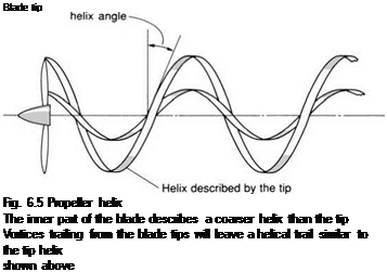
Any point on a blade describes a helix as it moves through the air, as shown in Fig. 6.5. The angle between the resultant velocity and the blade rotation direction is called the helix angle (see Figs 6.4 and 6.5). It will be seen that the
 Resultant relative
velocity
Fig. 6.4 Propeller geometry
 |
The resultant aerodynamic force on the blade section can be resolved into thrust and resistance
inner part of the blade is describing a coarser helix than the tip. If all sections of the blade are to meet the resultant velocity at the same effective angle of attack, the blade will need to be twisted, so that the geometric pitch angle (defined in Fig. 6.4) is greater near the hub than at the tip. The blade twist can be seen in Fig. 6.6.
|
Fig. 6.6 Advanced six-bladed high-aspect-ratio propellers on the Lockheed Super Hercules The inner part of a propeller blade describes a coarser helix than the outer, so the blades are twisted along their length. The spinner covers the ineffective drag – producing centre, and also houses the pitch-varying mechanism. In this picture, the blades are feathered (turned edge-on to the wind) to prevent them from windmilling when the aircraft is parked. The turbo-prop engine, unlike the piston engine, has little resistance to turning when not in operation |
The production of thrust by a propeller blade is similar to the generation of lift by a wing. It therefore follows that the blades will produce trailing vortices. Since the blades are rotating, however, the trailing vortices take the form of helical trails.


