Resultant Flow Velocity over Blade Element in the Hub Rotation Plane
It is well known that in the vertical flight regime each blade element is in a stream whose velocity is equal to the circumferential velocity of the element u = шг.
The situation is different in the forward flight regime. If the main /45
rotor angle of attack A = 0° , the resultant velocity with which the stream flows over the blade element depends on the element circumferential velocity, the
 flight speed, and the azimuth angle p. In this case the resultant velocity will not be equal to the geometric sum of the circumferential velocity and the flight velocity, since only the flow directed perpendicular to the blade longitudinal axis has an influence on the aerodynamic forces of the element.
Therefore, we must take as the resultant blade element velocity in the forward flight regime the sum of the vectors of the circumferential velocity of the blade element and the projection of the flight velocity vector on the line of the circumferential velocity vector (Figure 31).
V/ = Vclnb. (16)
Consequently, for a constant flight speed and constant angular velocity the resultant velocity will vary as a function of the azimuth angle.
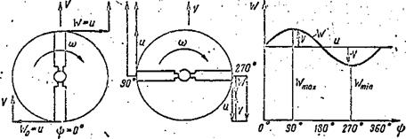
Let us examine the variation of the resultant velocity as a function of blade azimuth (Figure 32) .
|
V I/ У
Figure 32. Blade element resultant velocity as a function of azimuth. |
It is not difficult to see that for ip = 0° and 180° the resultant velocity equals the circumferential velocity, since the projection of the flight velocity on the circumferential velocity vector equals zero (Figure 32a)
W0 = U+V sin 0° == U,
V/m = u + Vsin 180° = U.
For ф = 90° the resultant velocity is /46
V7fl0 = и + V sin 90° = U – f – V.
For ф = 270° the resultant velocity equals the difference of the velocities (Figure 32b)
y270 — u-i-V sin 270° = 11- V.
If we use (16) to calculate the resultant velocity for several azimuths, we can plot the relation W = f(4>) (Figure 32c).
Figure 32 makes it possible to conclude that:
the maximal blade element velocity will occur at ip = 90°, the minimal will occur at ip = 270°; for ф = 0° and 180° the resultant velocities of a given element are equal to the circumferential velocity of this element. Consequently, the forward flight regime differs from the vertical flight regime in the variation of the blade element velocity. In the vertical flight regime this velocity remains constant W = u and is independent of the azimuth. In this regime the "blade azimuth" concept has no meaning. In the forward flight regime the resultant blade element velocity in the hub rotation plane varies continuously.


