Our heavyweight helicopter equal in the world does not have
In Rostov started production of the most load-lifting rotary-wing car The Russian holding «Helicopt[...]

Everything about aircrafts and helicopters. News and events in aviation worldwide. Civil, transportation, military helicopters and airplanes.

Everything about aircrafts and helicopters. News and events in aviation worldwide. Civil, transportation, military helicopters and airplanes.

Everything about aircrafts and helicopters. News and events in aviation worldwide. Civil, transportation, military helicopters and airplanes.

Everything about aircrafts and helicopters. News and events in aviation worldwide. Civil, transportation, military helicopters and airplanes.


|
h*(x)v(x) |
In the steady flow case, the one-dimensional formulation for a wing with endplates in the extreme ground effect can be simplified. We rewrite equation (4.53) for steady flow as
or, in a more compact form,
![]() -^[h*(x)v(x)] + 2Se^ signp(j)^/|p(a;)| = 0,
-^[h*(x)v(x)] + 2Se^ signp(j)^/|p(a;)| = 0,
where v(x) = (Іф/dx is the spanwise averaged flow velocity under the wing, h*'{x) = h*/h, h*(x) is the chord wise distribution of the clearance between the wing and the ground, h = h*(0) is the relative ground clearance at the trailing edge, and Sep and Sf are the effective gaps under the endplates and rear flap. Equation (4.65) is an ordinary differential equation of the first order with respect to the function v(x). The boundary condition follows from (4.57) for U(t) = 1 and takes the form
v(0) = —5f, = Sf/h.
![]() Equation (4.66) with boundary condition (4.67) can be easily solved numerically. In particular cases discussed later, it can be integrated analytically. Writing Sep as Sep(x) = 5lpA(x), where 5°p is the effective gap under the endplate at the trailing edge of the wing and function A(x) = 0(1) characterizes the form of distribution of local gap in longitudinal direction, we can rewrite equation (4.65) in the form
Equation (4.66) with boundary condition (4.67) can be easily solved numerically. In particular cases discussed later, it can be integrated analytically. Writing Sep as Sep(x) = 5lpA(x), where 5°p is the effective gap under the endplate at the trailing edge of the wing and function A(x) = 0(1) characterizes the form of distribution of local gap in longitudinal direction, we can rewrite equation (4.65) in the form
h(x)v(x) + GA(x) sign [1 – v(x)2]/|l – v2(x) = 0, (4.68)
which incorporates a similarity criterion G,
2 S°
G = – г-—. (4.69)
Ah
This criterion, which can be called a generalized gap parameter, reflects the combined influence on the leakage from under the wing of three important quantities, namely, the gap under the tips of endplates 5°p, the aspect ratio of the wing Л and the characteristic relative ground clearance h. It follows from (4.68) and (4.69) that within the mathematical model under consideration, the aerodynamics of the wing with endplates depends on G, rather than on £°p, Л, and h separately.
For G = 0, the flow under the wing in the extreme ground effect can be viewed as almost one-dimensional. Note that function h*(x) in a sufficiently general case can be presented in the form
N
h*(x) = 1 + 0x + ‘^£j fj(x), (4.70)
j=l
where в = в/h, в is the angle of pitch, Ej = O(h) and fj(x) = 0(1) are parameters and functions characterizing deformation of the lower surface of the wing, Ej — £j/h = 0(1), 0 = 0(1), and Ej = 0(1). For example, if the lower surface of the wing has the form of a parabolic arc with a relative curvature of 5C, the corresponding contribution to the sum in formula (4.70) is equal to 45cx(l — x), where Sc = Sc/h. It follows from (4.68)-(4.70) that the channel flow velocity v(x) and, consequently, the other aerodynamic characteristics (pressure coefficient, forces, and moment) should depend upon G and the set of parameters 0,5f, Ej, (j = 1,…, N).
The lift and moment coefficients, as well as the abscissa of the center of pressure, are represented by the expressions
|
xp ~ p * |
|
|
|
|
As discussed previously, the leakage of the flow from under the endplates leads to generation of vorticity and, consequently, induced drag. For a steady lifting flow in the extreme ground effect, it follows from (4.64) that
We consider some analytical solutions of the main equation for steady flow. In some practically interesting cases, equation (4.65) with condition (4.67) can be integrated in closed form.
Let the effective gap under endplates 5ep be constant chordwise. Note that, if one defines the effective gap as a geometric gap under the endplate, the above assumption implies chordwise uniformity of the latter. If one introduces the outflow contraction model, the effective gap would depend on the ratio of the geometric gap to the local ground clearance h*(x), and, consequently, would vary chordwise even when the geometric gap is constant. However, for small magnitudes of the relative geometric gap, the effective (contracted) gap can be considered practically constant for a given setting of the endplate (or flap) with respect to the ground plane. We set A = 1 in equation (4.68), so that <5ep(x) = = const.
We consider some closed form results for the flow with leakage.
We turn to consideration of the simplest case of a flat rectangular wing at zero pitch angle в = 0 with endplates and a rear flap. In this case the lift of the wing is due to deflection of the flap (5f ф 0). Because both the local ground clearance and the distance from the tips of endplates to the ground are constant chordwise (h*(x) = 1 and Sep(x) = <^p)> equation (4.68) takes the form л
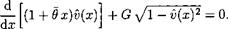
+ Gy/l-v(x)2 = 0. (4.75)
dx
Note that both signum function in front of the square root and the absolute value sign under the square root were omitted because in this case one expects no suction under the wing, so that v(x) < 1.
The integral of (4.75), complying with boundary condition (4.67), is given
by _
v(x) = — sin (Gx + arcsincJf). (4-76)
The distribution of the pressure coefficient p(x) along the channel under the wing can be obtained by the formula
The lift and moment (with respect to the trailing edge) are given by the expressions
With reference to (4.74), the induced drag coefficient may be found as
Cx. = /і j[l – sin(G + arcsinJf)]2 – (1 – 5f)2 j, G = -—jp. (4.80)
As seen from these formulas, in the example under consideration the aerodynamic characteristics of the wing depend on only two parameters, namely G and Jf. At the same time, the original problem contained four parameters, including the relative ground clearance h, the aspect ratio Л, the effective gap under the endplates 5°p and the effective gap under the flap 5f. Thus, in this example, the use of similarity criteria reduces the number of independent parameters of the problem twofold! Generally, for a uniform distribution of the gap under the endplates along the chord, the number of parameters that characterize the flow problem for h —> 0 will be n — 2, where n is the initial number of parameters.
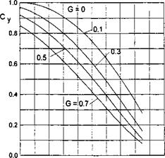
The lift coefficient Cy and the abscissa of the center of pressure xp = mz/Cy versus the similarity criteria 5f and G = 2£°p/A/i are plotted in Figs. 4.8 and 4.9. Plotted in Fig. 4.10 against the similarity parameter G for different flap settings is the induced drag coefficient CXi related to h.
Another integrable case is that of a flat plate at pitch angle 0 with endplates at a constant gap <5ep(a;) = 5ep and a short rear flap. In this case, the ground clearance function h*(x) = 1 + Ox, 9 = в/h, and equation (4.68) yields
 (4.81)
Rewriting (4.81) as
![]() (1 + Ox) -—h 9v(x) + G y/ — v(x)2 = 0, ax
(1 + Ox) -—h 9v(x) + G y/ — v(x)2 = 0, ax
we can separate the variables in the following way:
![]()
|
 |
0.0 0.2 0.4 0.6 0.8 – 1.0
Sf
Fig. 4.9. The abscissa of the center of pressure of a wing with endplates at zero pitch angle versus the trailing edge flap setting for different magnitudes of similarity criterion G = 2<5eP/A/i.
Introducing the alternative similarity parameter Gq,
we obtain from (4.84)
|
G* exp ^ |
 |
|
It follows from the preceding calculations that the solution of the basic equation is dependent on a pair of parameters, in particular, G = 25°p/A/i and 0 = 0/h, or on an alternative pair of parameters Gq — 2J°p/A0 and 0. It is worthwhile mentioning that parameter G#, discussed herein, is identical to parameter H, introduced by Gallington et al. [61]. The integral of equation (4.85) can be obtained in closed form. The result in the form of an implicit relationship x = x(v) can be written as
|
C* = exp So, finally, Ox — exp where L(v, Go,8f) = In |
 |
Applying the boundary condition (4.67), we can determine the constant C* as
|
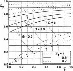
Fig. 4.11. The lift coefficient of a wing with endplates versus pitch angle for different magnitudes of similarity criterion G = 25°p/h and flap settings. |
|
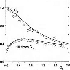
Fig. 4.12. The lift and drag coefficients of a rectangular wing with endplates versus parameter G$ = 25^р/Х0: theory and experiment (Л = 0.5; circles: experiment [61]; solid lines: present theory; dashed lines: G-theory). |
The structure of (4.88) shows that in the example under discussion the solution (span-averaged velocity and pressure coefficient) depends on a new independent variable x = 6x and the similarity criteria Gq and <Sf, i. e.,
v = v{xi, Ge,8{), p = p(x1,Ge,6{).
![Подпись: Fig. 4.13. The lift-to-drag ratio of rectangular wings with endplates: theory and experiment (empty circles: experiment for Л = 2/3 [61]; black circles: experiment for Л = 0.5 [61]; solid lines: present theory; dashed lines: G-theory).](/img/3131/image411.gif) |
The coefficients of lift, longitudinal moment (with respect to the trailing edge) and the abscissa of the center of pressure are calculated by the formulas (4.71)-(4.73).
The flow model, described by equation (4.82) with boundary condition (4.67), contains as a particular case the previously mentioned G-theory, proposed by Gallington et al. [61]. The latter theory, based on elementary continuity considerations, implies that the pressure does not vary along the chord of the wing.
To retrieve the governing equation of the G-theory from equation (4.82), suppose that a solution of this equation exists, for which the span-averaged velocity (pressure) is constant along the chord, i. e., v(x) = const. = v. Then, for a flat rectangular wing with a constant gap under the tips of the endplates and pitch angle 0, equation (4.82) can be rewritten as
_____________________ 25°
v + GgV l-v2 = 0, = (4.89)
Ли
Equation (4.89) can be easily solved with respect to v to give
It follows from (4.90) that the both pressure and lift coefficients in the G- theory depend only on parameter G^, i. e., are defined in terms of a certain combination of the gap under the endplates, the aspect ratio and the adjusted
pitch angle of the wing. On the other hand, (4.89) provides a simple tool for designing a ram wing vehicle for a given pressure in the channel At the same time, the assumption of constant v together with prescribed boundary condition (4.67) necessitates the following equalities:
indicating that the rear flap should be “tuned up” to ensure the prescribed pressure in dynamic air cushion. These relationships show, in particular, that an increase in the design ground clearance for the same magnitude of loading should be followed by an opening of the gap.
The foregoing approach to determining the aerodynamic characteristics of rectangular wings with endplates in the extreme ground effect remains valid for foils with local suction. One example of such a foil is illustrated in Fig. 4.14, which shows the lift coefficient versus the generalized gap parameter G for a foil with a parabolic lower surface and zero pitch angle. Other examples of calculation of the aerodynamic parameters of foils with local suction are discussed in the next section in connection with the problem of the static stability of longitudinal motion.
Now, we turn to the case when the generalized gap parameter is equal to zero, i. e., G = 0. Note that this can occur either for zero clearance under the tips of the endplates 5ep = 1 or when the wing has an infinite aspect ratio (A -> oo). For <jf = 0, the latter case corresponds to the description of the order of 0(1) of the two-dimensional flow problem for a foil moving close to the ground, as discussed in paragraph 4.1.
 o. o
o. o
Су
-0.2 -0.4 -0.6 -0.8 -1.0
In this case, the equations (4.65) and (4.67) can be rewritten as
![]() h*(x)v(x) = 0, v(0) = —5f.
h*(x)v(x) = 0, v(0) = —5f.
ax L J
|
h*(x) |
|
h*(x)- |
|
h*2(x) |
The solution of problem (4.90) is elementary,
Here are some simple analytical expressions for Cy and mz for some particular cases:
|
-p – 2* Flat plate without a flap <5f = 1 at a given incidence 6: c =J – y l + e’ |
Flat plate with a rigid flap at zero pitch:
Note that for small perturbations these formulas yield corresponding expressions of the linear theory, whereas for moderate and large perturbations, they reflect the inherent nonlinearity of the aerodynamics of the extreme ground effect.
• Flat plate at pitch angle 9 with a rigid flap
Employing formula (4.63), it is easy to find the suction force coefficient as
Cs = h(l + 9)(l-j^y. (4.97)
Because for G = 0 (no gap under the endplates or an infinite aspect ratio) there is no lateral leakage, the overall drag force acting on the wing in potential flow should be zero. Taking into consideration the magnitude of the pressure drag coefficient for this case,
CXp = – Cye + CXp( =-he(l-^L)-h(l-8f)2, (4.98)
we obtain the following result:
CXi = CXp + Cs
= – M(l – – Ц1 – 6f)2 + /1(1 + 0)(1 – y^)2 = 0, (4.99)
which confirms the correctness of the determination of the suction force coefficient.
• Flat plate with incidence and a jet flap at the trailing edge:
In this case, the corresponding effective gap under the jet flap entering the problem can be determined from local analysis of the flow near the jet flap (see section 6) as
where Cj is a coefficient of the total momentum of the jet and r is the angle of blowing.
Substituting with <5jf in expressions (4.96), as given by (4.100), we obtain the following formulas for the aerodynamic coefficients of a a foil with a jet flap at the trailing edge:
![]()
а – т^сдщ2
The induced drag coefficient of a jet-flapped rectangular wing with end – plates at pitch angle 9 can be found from (4.74) with Sf replaced with the effective gap under the jet flap 5^; see (4.100). In the particular case of zero incidence, we obtain the following expression:
CXi = /ij[l – sin(G + arcsin5jf)]2 – (1 -^f)2j, <$jf = Ty 7^- (4.ЮЗ)
It is interesting that introduction of the effective gap under the jet flap <5jf renders identical the structure of the formulas for predicting the aerodynamic coefficients in the cases of a wing with a rigid flap and wing with a jet flap.