Supersonic wing shapes – plan form
In flight at subsonic speeds the shape of the aerofoil section is in some respects more important than the plan form of the wing, but at supersonic speeds it is the plan form which is the more important (Fig. 12B, overleaf). On the other hand, the more one studies the seemingly endless variety of both aerofoil section and plan form that are not only possible but seem to have proved successful in supersonic flight, the more one is forced to the conclusion that neither shape matters very much; supersonic flow is more accommodating than subsonic flow, less fussy in what it encounters, and although, compared with subsonic flow, the lift coefficient is less, the drag coefficient greater, and the LID ratio in consequence lower, the actual values of CL, CD, and LID, and the position of the centre of pressure seem to be little affected by the shapes of either the cross-section or the plan form of the wing.
Tet us consider first the plan form. It will be remembered that in the transonic region there was advantage in a considerable degree of sweepback of the leading edge because it delayed the shock stall, the increase of drag, buffeting, and so on – in other words, it raised the critical Mach Number. It is often stated that there is no advantage in sweepback after the critical Mach Number has been passed, and that straight wings are better for supersonic flight. This might be true if the only effect of sweepback was to delay the critical Mach Number – but actually it does more than this.
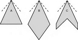
Consider, for instance, the plan shapes А, В, C, and D (Fig. 12.16, overleaf); with the possible exception of B, all these have been used on high-speed aircraft. At the apex of each are shown the Mach Tines for a Mach Number of about 1.8, and it will be noticed that the leading edges for these shapes all lie
within the Mach Cone, and this in turn means that the airflow which strikes the wing has been affected by the wing before it reaches it; if, as is probable, there are also shock waves at the nose of the aeroplane, or at the apex of the wing, the whole of the leading edge of the wing will be behind these shock waves and so will encounter an airflow of speed lower than that of the aeroplane. This airflow may not be actually subsonic, but at least the resolved part of it at right angles to the leading edge, or across the chord, is likely to be. So although a swept-back wing is better than an unswept wing in the transonic region, it may retain some of its advantages even into the supersonic region – and this applies particularly to thick wings which are naturally more prone to the formation of shock waves.
 |
 |
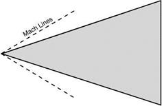
Of course, if we are to keep within the Mach Cone the sweepback must increase with the Mach Number, until eventually the delta shape may be more appropriately described as an arrow-head shape (Fig. 12.17).
 |
Fig 12.16 Supersonic wings – plan shapes
Fig 12.17 Arrow-head delta wing for high Mach Numbers
Fig 12B Supersonic configuration (opposite)
(By courtesy of British Aerospace Defence Ltd, Military Aircraft Division.) The Typhoon Eurofighter prototype with delta wing and canard foreplane for control.
FLIGHT AT SUPERSONIC SPEEDS
But whenever we discuss the advantages of sweepback we must never forget its disadvantages which are largely structural; the twisting and bending stresses on a heavily swept-back wing give many headaches to the designer and mean extra weight to provide the strength. But there is also the old bogey of tip stalling and lateral control near the stalling – and landing – speed. Shapes A and В are better structurally than C and D, they are better, too, from the point of view of tip stalling; they also have an interesting, though perhaps rather concealed, advantage in that owing to the long chord the wing can be thick (which means a good ratio of strength to weight), yet still slim as regards thickness/chord ratio (which is what matters as regards shock drag). Have C and D then no advantages? – it would be strange if they hadn’t, because they are in fact more common in practical aeroplanes than B, until recently than A also, but A is becoming increasingly popular in modern designs for supersonic transport. The advantage of C and D lies chiefly in lower drag (in spite of the point mentioned above), and so in better lift/drag ratio; they are also more suitable for the conventional fuselage and control system (if that is an advantage), and for engine installation.
One rather unexpected bonus resulting from the use of delta wings, or others with extreme taper and sweepback of more than 55° or so, comes from the stall itself; this is a leading edge stall which starts at the wing tip and progresses gradually inboard, the separation bubble is then swept back with the leading edge and shed as a trailing vortex, tightly rolled up and with a very low pressure at its core. The low pressure acts on the forward facing parts of the upper surface of the wing giving a ‘form thrust’ (in effect a negative drag) and a lift boost; moreover the flow in the core is stable and causes little buffeting, unlike the separation vortex on wings with sweepback of less than 50°. This is, in fact, an effective way of producing lift. Concorde used it at both subsonic and supersonic speeds. The use of fences, saw teeth and vortex generators can, at best, only give partial mitigation of the resulting stalling phenomena such as the buffeting, wing drop and pitch up.
But whatever the pros and cons of sweepback there is no doubt that there is a lot to be said for the straight rectangular wing for really high supersonic speeds (Fig. 12.18). With the small aspect ratio, and tremendously high wing loading associated with such speeds, the wings are very small anyway, and from the strength point of view a rectangular wing, or a wing that is tapered for structural reasons rather than for aerodynamic reasons, will probably win the day.
Figure 12.19 shows how only small portions of a rectangular wing at supersonic speeds (the shaded areas) can know of the existence of the tips, and these portions will tend to exhibit the normal characteristics of 3-dimensional subsonic flow, wing-tip vortices, etc., while the flow over the remainder of the wing will be straight 2-dimensional flow as if the wing was of infinite span and there were no wing tips. This leads to a rather obvious suggestion – cut off the shaded portions.
This, in fact, is sometimes evident in design, but the arguments one way and another, for sweep at leading or trailing edge (or both, or neither), for delta
|
|
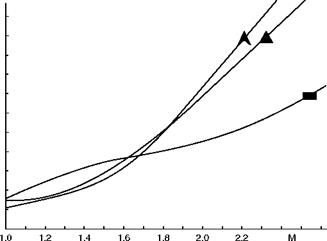
Fig 12.18 Wing shapes and drag
How the drag increases with Mach Number for straight, highly-swept and delta wing shapes.
and arrow plan forms, for tail first or wing first, for tail to be larger or smaller than the wing, even to decide which is the wing and which the tail – that these arguments are endless is clearly evident from the numerous shapes and configurations which have been tried or suggested for missiles or supersonic aeroplanes.
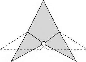
The fundamental difficulty, for aircraft rather than missiles, is to provide wings that are suitable not only for supersonic flight, but also for subsonic and transonic flight. After all, supersonic aeroplanes have to take off and land; and they also have to pass through the transonic region. The real answer – so far as plan form is concerned – is surely in variable sweep (Fig. 12.20, overleaf); advocated many years ago by an eminent British inventor but, as so often
Direction of flight
|
|
Fig 12.19 Rectangular wing at high Mach Numbers
|
|
Fig 12.20 Variable sweep
happens, left to others to put into practice; the Americans had serious teething troubles with their first real effort in this direction, the General Dynamics swing-wing F-lll, of which so much was expected. Perhaps as a result of this disappointment, the Boeing idea of a swing-wing supersonic transport was also abandoned. Nor, in the meantime, were the French initially successful with their Mirage G (Fig. 12C, overleaf), but accumulated experience pays off and the variable sweep concept has been adopted for a number of aircraft including the Tornado.
The design process is finely balanced though; a great number of solutions to the problem of supersonic flight abound, such as the simple long-nosed delta configuration of the Anglo-French Concorde (Fig. 12D, overleaf).


