The Ducted Propeller at an Angle of Attack
At the present time no particular method exists for predicting the aerodynamic behavior of a ducted propeller at extreme angle of attack. The problem is a difficult one because of the dominant role of real fluid effects. About the best that can be done is to examine in a qualitative sense the experimental results that have been obtained to date.
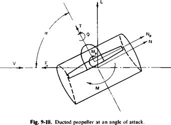
Figure 9-18 shows the system of forces and moments acting on a ducted propeller at an angle of attack taken from Ref. 8. Consider what might be expected for the behavior of this force system as a. is increased from zero. The duct behaving as a ring airfoil would produce a lift. Solutions of the ring airfoil appear in the literature based on various mathematical models. For example, Ref. 9 presents a theory comparable to lifting line theory for planar wings and predicts that the lift of a ring airfoil is twice the lift of an elliptic wing with a midchord equal to the chord of the ring airfoil and a span equal to the diameter of the ring airfoil. Hence, if CL for the ring airfoil
is based on its projected planform area, then dCJda is predicted to be
dCL _ 2 nDC/4 /dCL da DC da /elliptic
or
![]() dCL = n /ЛСЛ da. 2da /elliplic’
dCL = n /ЛСЛ da. 2da /elliplic’
 |
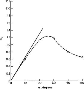
(dCL/da)eUiptic is the slope of the lift curve of an elliptic wing with an aspect ratio equal to 4D/nC and can be obtained from Fig. 3-17 or Eq. (3-55). A comparison between (9-32) and the experimental results of Ref. 8 is pre
sented in Fig. 9-19 by using Eq. (3-55) and a section lift curve slope of 0.1C,/degree. It can be seen that the performance of the ring wing is predicted closely by Eq. (9-32).
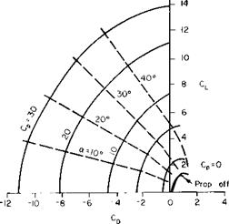
Adding a thrusting rotor to the duct does not increase the lift of the duct by the vertical component of the rotor thrust. In fact, the lift of a ducted propeller is considerably more than the sum of the lift on the duct alone and the vertical component of the total thrust. At this stage of development, it appears to be somewhat dangerous to attempt to generalize on the experimental results available. Instead, a few typical results are discussed. Figure 9-20, taken from Ref. 10, presents in one rather convenient manner the lift-thrust-power angle-of-attack relationship for a particular ducted propeller. Here CD versus CL is plotted for several constant values of a power coefficient Cp. Contours of constant a are also shown; Cp is defined as the power divided by pV*S, S being the projected planform area of the
shroud. In such a presentation the vector from the origin to a point on the contour represents the resultant dimensionless force vector for that set of operating conditions. As Cp increases, any velocity induced by the rotor would become large in comparison with the free-stream velocity and the
|
Fig. 9-19. Lift curve of a ring airfoil:————– Eq. (3-55); —e— Ref. 8, Fig. 8; C = 10.31 in.; D = 16.90 in. |
|
|
resultant force would be expected to be a constant independent of a. This expected behavior is confirmed by the constant Cp curves becoming more circular as Cp increases.
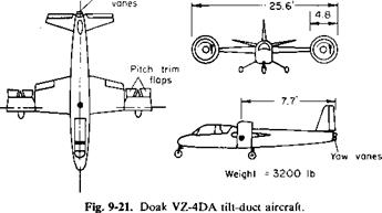
Actual flight tests of a tilt-duct aircraft, the Doak VZ-4DA, are reported in Ref. 11. A sketch of the aircraft is presented in Fig. 9-21. Its two ducts have an inside diameter of 4 ft and a chord of 2.75 ft and are rotatable through an angle of 92°.
Flight test data were obtained on both power required and handling performance. Because the resultant-force vector produced by the ducted
|
Pitch control
|
|
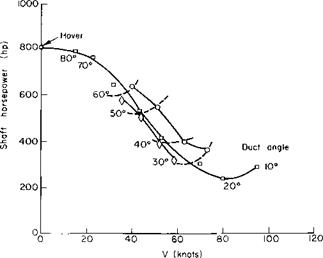
Fig. 9-22. Power required through transition speed range for Doak VZ-4DA. awing, degrees: О = 2.5; □ = 6.5; 0 = 10.5; constant awjng; constant aducl. |
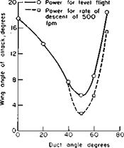
propellers can be varied, the lift required of the wing in level flight at a given speed can be varied. Hence the power required by the aircraft to maintain level flight depends on the angle of attack of the ducts in relation to the aircraft. These results are shown in Fig. 9-22, in which it appears that the least power is required when the wing is operating at the higher angles of attack. Of course, this is in the transition speed range and power is probably of a secondary consideration anyway. Perhaps the most important fact to note is that the power required is a maximum at V = 0 and decreases continuously without any abrupt changes to the normal aircraft configuration.
 |
|
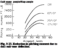
Of more importance is how the aircraft handles through transition. Is the longitudinal control sufficient and does the aircraft experience buffeting due to stalling on the wing or ducts? A ducted propeller at an angle of attack produces a significant nose-up pitching moment. Data on this for
the Doak VZ-4DA ducted-fans presented in Fig. 9-23 are taken from wind – tunnel studies reported in Ref. 12. These data are for a constant wing angle of 2° at the power required for steady level flight. As shown in the figure, by installing a small vane in the slipstream of the duct the nose-up pitching moment can be reduced by a factor of 2.
The stalling or buffeting boundaries determined from the flight tests of Ref. 11 are shown in Fig. 9-24. In a comparison of this figure with Fig. 9-22 it is found that the aircraft is the most critical with respect to stall at a speed of approximately 45 knots. The stalling occurs on that portion of the wing closest to the ducts, apparently the result of an upwash induced at the wing by the ducted propeller.
The lack of an adequate theory to predict the behavior of a ducted propeller at angles of attack is probably not too serious. We can estimate its static performance in hover and its performance in the full nose-down position on the basis of the considerations given earlier. For intermediate positions some “eyeballing” based on Figs. 9-20 and 9-22 can be done.
|
Fig. 9-24. Effect of power on stall onset boundaries. |


