Von Karman Momentum Integral Equation
 |
The solution of the boundary layer equations, although more palatable in these days of computers, can still prove to be a formidable task in the general case of suction and when dp/dx is not zero. To circumvent these difficulties, a method, attributed to von Karman, is often used in which the
momentum theorem is applied to the gross characteristics of the boundary layer.
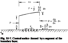
Consider Fig. 10-7. A control surface is formed by a differential segment of the boundary layer. The flux entering the left face of the control surface is
![]()
![]() ■a
■a
 |
The flux passing out through the right face can be written
The flux removed by suction is
Qs = v0 dx.
Because the flux in must equal the flux out, Q3, the flux in along the top, can be calculated from
 |
or
The fluid along the top being drawn in has a velocity in the x-direction of Ux. Thus the total flux of momentum in the x-direction coming in is
The total momentum out is
The sum of the forces in the x-direction acting on the fluid around the control surface is
Z К = PS + (p + fx *)f Л – (p + fx *)(<5 + fx *) – •. *.
|
– * U."" |
 |
||
where t0 is the shear stress at the wall. Equating ZF* = Momout — Momin and dropping higher-order terms produces the following:
However, from the definition of the displacement and momentum thicknesses
![]()
U dy = 11^(6 – 5*1
Substituting the above in (10-19) and relating p and UrXj by Bernoulli’s equations, we obtain
uj* ^ + T – + u^0 = -• (10-20)
dx ax p
Equation (10-20) is known as the von Karman momentum integral equation (modified for suction) and relates the displacement and momentum thickness to the wall shearing stress and the velocity U^. It applies equally well to laminar and turbulent boundary layers. For a Newtonian fluid such as air or water the wall shearing stress r0 for laminar flow is given by
(10-21) where p is the coefficient of viscosity.
The advantage in using Eq. (10-20) lies in the fact that the results do not depend to any great extent on the form of the velocity distribution u(y). We can assume a и(у) and by satisfying Eq. (10-20) relating the gross characteristics arrive at reasonable values of these quantities.
For example, consider a flat plate with no suction; (10-20) becomes
dO r0
dx pUi
Now assume an extremely crude profile, namely, a straight-line variation from 0 at the wall to U„ at у = <3.
и у
u^ = s’
For this distribution 9/8 = 5, 8*/8 = and t0 = p(U^/8). Hence (10-20) becomes
d5 6p
dx pUj
 |
or integrating and substituting for в and 8* gives
These results agree surprisingly well with Blasius’ exact solution. Even the wall shearing stress is only about 13% lower than that calculated by the exact method.
Karman-Pohlhausen Method
We represent the velocity profile by a fourth-degree polynomial in terms of the dimensionless distance from the wall, h = y/8.
-j— = ah + bh2 + ch3 + dhA. (10-22)
on
The constants a, b, c, and d are determined from the following boundary conditions. From Eq. (10-1)
![]() at у = 0.
at у = 0.
 |
||
At у = ё, и = Uди/ду = 0, 82и/ду2 = 0. From these boundary conditions the constants are found to be
where
<52 «Л/, „
=—– j—> P =—–
v ax v
In terms of a, b, c, and d, the displacement and momentum thickness are given by
|
s* |
1 a- b– 2 3 |
c |
d |
|
|
5 |
4 |
5 |
||
|
9 S ~ |
1 + 1 |
a2 3 |
ab У “ |
2ас + b2 5 |
![]() ad + be 2bd + c2 cd d2
ad + be 2bd + c2 cd d2
3 7 ~4 ~ ~9
Equation (10-20) can now be solved numerically, given UrJx). At each x, Rd, and the shape factors H or К are calculated and R6. compared with R6irjt from Figs. 10-4 and 10-5. In this manner the point of transition can be determined or the amount of suction required to delay transition can be calculated.


