Our heavyweight helicopter equal in the world does not have
In Rostov started production of the most load-lifting rotary-wing car The Russian holding «Helicopt[...]

Everything about aircrafts and helicopters. News and events in aviation worldwide. Civil, transportation, military helicopters and airplanes.

Everything about aircrafts and helicopters. News and events in aviation worldwide. Civil, transportation, military helicopters and airplanes.

Everything about aircrafts and helicopters. News and events in aviation worldwide. Civil, transportation, military helicopters and airplanes.

Everything about aircrafts and helicopters. News and events in aviation worldwide. Civil, transportation, military helicopters and airplanes.


Flight in the vortex ring state is characterized by very unstable flow conditions, which produce vibration and erratic thrust variations. Flight test experience on a small tandem rotor helicopter reported in reference 2.3 showed that the characteristic vibration began at a rate of descent equal to about 23% of the hover – induced velocity and persisted until the rate of descent exceeded 125% of the hover-induced velocity.
For the example helicopter, these boundaries would cover the region between 400 and 2,900 ft/min rate of descent. The results also showed that for the test helicopter, forward speeds above about 10 knots were sufficient to avoid vortex ring vibration at all rates of descent. Similar tests on a larger single-rotor helicopter reported in reference 2.4 showed that a forward speed of 25 knots was enough to avoid the vibration. Thus, in flight, it is relatively easy to get out of the vortex ring state by flying with a small amount of forward speed. As a matter of fact, it is a fairly difficult piloting task to stay in the vortex ring state for any length of time.
![]()
|
|
|
|
|
|
|
|
|
|
|
![]()
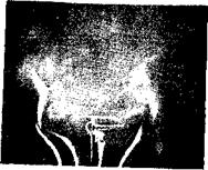
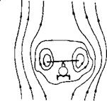
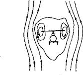
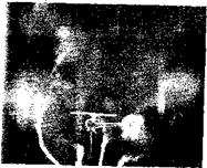
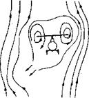
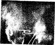
Source: Drees & Hendal, "Airflow Patterns in the Neighborhood of Helicopter Rotors,” Aircraft
Engineering, Vol. 23, April, 1951. Photos courtesy of MLR.
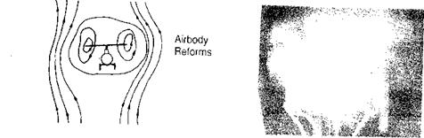
The instability of the vortex ring flow studied with smoke going through a model rotor in a wind tunnel was reported in reference 2.5. Two observations in that report are of interest in visualizing the flow. The first speculates about an effective airbody within which air is circulated by the rotor, as shown in Figure 2.5. The airbody is originally roughly spherical; but, as the rotor pumps energy into it, it lengthens downward until it bursts like a bubble, permitting the accumulated energy to dissipate into the surrounding upward-moving air. The airbody then returns to its original shape and starts the cycle again. The fluctuating airflow, of course, makes the thrust and/or rate of descent also fluctuate. The other observation based on a study of the smoke pictures (especially vivid in the motion pictures made during this study) is that the airflow fluctuations are not symmetrical around the rotor. Figure 2.5 shows several frames from the smoke movies during a steady vortex ring condition. The vortex can be seen to be formed first on one side and then on the other in a completely random fashion. Thus not only does the rotor thrust fluctuate, but so also does the flapping as the rotor responds to the changing inflow patterns.
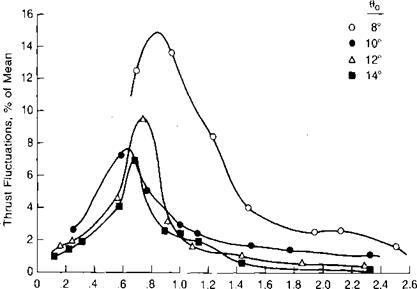
The magnitude of the vortex ring flow fluctuations as measured on a model rotor in a wind tunnel are reported in reference 2.6 and are shown in Figure 2.6. The region of roughness is about the same as that found in flight test. A theoretical study of the vortex ring state presented in reference 2.7 concludes that the maximum wake instability should occur for the condition in which the tip vortices stay in the plane of the rotor. Reference 2.7 shows by a momentum
|
|
V<> v’ ho»
FIGURE 2.6 Thrust Fluctuations in Vertical Descent
Source: Azuma & Obata, "Induced Flow Variation of the Helicopter Rotor Operating in the Vortex Ring State,” Jour, of Aircraft, July-August, 1968.
m
analysis that this condition exists when the rate of descent is equal to 0.707 times the induced velocity in hover. This conclusion is verified by Figure 2.6. A further study of vortex ring theory is presented in reference 2.8.
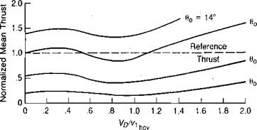
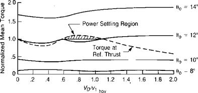
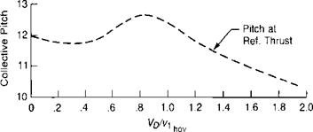
The experimental data of reference 2.6 also illustrates the phenomenon known to pilots as power settlings where more power is required to descend than to hover. Figure 2.7 shows normalized thrust and torque values as a function of the vertical descent velocity ratio. A reference thrust level has been selected— corresponding to hover at 12° of collective pitch—and the required collective
|
|
|
|
|
FIGURE 2.7 Effect of Rate of Descent on Rotor Conditions |
Source: Azuma & Obata, “Induced Flow Variation of the Helicopter Rotor Operating in the Vortex Ring State,” Jour, of Aircraft, July-August, 1968.
pitch and torque as a function of rate of descent have been found by crossplotting. It may be seen that both the required pitch and torque first decrease, as would be expected, and then increase in the region of maximum flow fluctuation before decreasing again as the rotor approaches autorotation. The power-settling condition is of practical importance if during a vertical takeoff of a multiengined helicopter, one engine fails and the pilot attempts to return vertically to the takeoff point. If during this return the pilot enters the power-settling region, the power required from the remaining engines—or the final impact velocity—will be higher than would be estimated from simple transfer-of-energy equations. This region also roughly corresponds to the region of negative thrust damping. A detailed analysis of vertical and near-vertical descent will be found in reference
2.9.
|
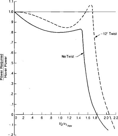
FIGURE 2.8 Effect of Twist on Power Required in Vertical Descen |
Source: Castles & Gray, “Empirical Relation between Induced Velocity, Thrust, and Rate c Descent of a Helicopter Rotor as Determined by Wind-Tunnel Tests of Four Model Rotors,” NAC TN 2474, 1951.
An as yet unexplained mystery is indicated by Figure 2.8, which presents an analysis of wind tunnel data reported in reference 2.10 for two model rotors, which were identical’ except for blade twist. The rotor with the twisted blades demonstrated a definite power-settling regime, whereas the rotor with untwisted blades did not. In addition, the authors comment: "Also, the fluctuations in the forces and moments on the rotor with twisted blades were very much larger at the higher rates of descent than for the rotors with untwisted blades.”

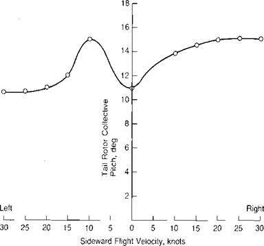
Vertical descent is not the only flight condition in which the vortex ring state is of importance. A tail rotor may be operated in the vortex ring state during sideward flight or during a hover turn over a spot. Figure 2.9 shows the tail rotor collective pitch as a function of sideward velocity for the UH-1 as reported in reference 2.11. The "lump” is attributed to the vortex ring state. In the region of neutral and negative slope to the left of hover, pilots find it very difficult to hold a steady
|
FIGURE 2.9 Tail Rotor Pitch Required in Sideward Flight |
Source: Lehman, “Model Studies of Helicopter Tail Rotor Flow Patterns In and Out of Ground Effect,” USAAVLABS TR 71-12, 1971.
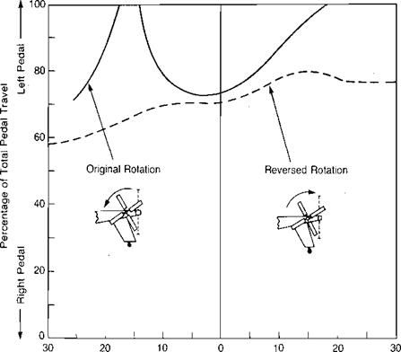
heading. Hover turns that put the tail rotor in this condition, create a situation that pilots call "falling into a hole.” The basic cause of this is best illustrated by the curves in the top portion of Figure 2.7. The curves are unstable between velocity ratios of 0.4 and 0.8, and any increase in the turn rate will lower the tail rotor thrust, thus increasing the rate even further. The hover-induced velocity for the UH-1 tail rotor is about 48 ft/sec. The maximum vortex ring effect would be expected to occur at 70% of this value or at about 20 knots. The fact that it occurs at a lower speed appears to be a result of the main rotor wake interacting with the tail rotor. Figure 2.10, taken from reference 2.12, shows a dramatic difference in pedal position in sideward flight resulting from a change in the direction of tail rotor rotation for the Lockheed AH-56A. Rotation with the bottom blade going aft apparently entrains the tip vortex of the main rotor, causing a premature vortex ring condition at the tail rotor. Rotation in the opposite direction seemed
|
Left Sideward Flight Right Sideward Flight Velocity, knots FIGURE 2.10 Typical Pedal Requirements for AH-56A in Right and Left Sideward Flight |
Source: Wiesnerand Kohler, “Tail Rotor Design Guide,” USAAMRDLTR 73-99,1973.
to cause an indefinite delay in the vortex ring condition resulting from a favorable interference of the main rotor tip vortex.
Experimental evidence of this interference is given in reference 2.13. Figure 2.11, based on that report, shows the pitch of the tail rotor required to balance main rotor torque as a function of sideward speed for four different model configurations. The top portion shows the effect of the presence of the main rotor and the lower portion shows the effect of tail rotor direction of rotation in the presence of the main rotor. The evidence of premature vortex ring conditions is not as dramatic as in the preceding two figures, but it is there.
Another study of left sideward flight motivated by some less-than – satisfactory sideward-flight characteristics discovered during the initial development flying on the Hughes AH-64 is reported in reference 2.14. Figure 2.12 shows the pedal activity required to hold heading in left sideward flight with two different tail configurations: a T-tail with a 100-inch diameter tail rotor and a stabilator with a 110-inch diameter tail rotor. The improvement observed with the second configuration was also present even when flown with the smaller tail rotor. Thus the beneficial change appears to be due to raising the tail rotor, which apparently made it less susceptible to effects from the main rotor tip vortices. Two further observations from this program are worth mentioning. The same test pilots who were investigating the unsatisfactory left-sideward-flight characteristics of the AH-64 with the T-tail found that a Huey Cobra that was available as a chase aircraft had no trouble in the same flight condition even with its stability augmentation system turned off! The Cobra tail rotor blades are untwisted, whereas those on the AH-64 have —8° of twist. The differences seem to correlate with the wind tunnel experience quoted during the discussion of Figure 2.8.
The other observation is that on the AH-64, pure left sideward flight was not the most critical condition. Instead, the unsteadiness was worse, with the aircraft flying about 20° off of pure left with the tail rotor leading the main rotor. Why this should be more critical than with the tail rotor following the main rotor is not known.