Constant-Strength Doublet Method
An even simpler method for lifting airfoils can be derived by setting the source strengths to zero in Eq. (11.60). The value of the constant for the internal potential is selected to be zero (since a choice similar to that of the previous section of Ф, = О» will result in the trivial solution). Consequently the boundary condition describing the internal potential (Eq. (11.60)) reduces to
Ісл + Ф. = 0 (11.81)
i=і
where
Ф* = Uax + W^z (11.82)
Note that now ц will represent the potential jump from zero to Ф„ on the boundary (see Fig. 11.26) and therefore Ф„ is the local total potential (whereas in the previous example fj, was the jump in the perturbation potential only).
Equation (11.81) can be specified at each collocation point inside the body, providing a linear algebraic equation for this point. The steps toward
establishing such a numeric solution are very similar to the previous method:
Selection of singularity element. For this case a constant-strength doublet element is used and the potential at an arbitrary point P (not on the surface) due to a constant-strength doublet is given by Eq. (11.64) and by the routine of Eq. (11.66):
![]() ЛФл = PHICD (juy, x, z, Xj, zj, xj+u z/+1)
ЛФл = PHICD (juy, x, z, Xj, zj, xj+u z/+1)
Discretization of geometry. The N + 1 panel comer points and N collocation points are generated in a manner similar to the previous example and a typical grid is shown in Fig. 11.18. Since in this case the internal Dirichlet boundary condition is used the collocation points must be placed inside the body (with a small inward displacement under the panel center—this inward displacement can be skipped if the self-induced influence is specified separately).
Influence coefficients. The increment in the velocity potential at collocation point і due to a unit strength constant doublet element of panel j is given by Eq. (11.68):
The construction of the doublet influence matrix and the inclusion of the Kutta condition (and the wake doublet nw) is exactly the same as in the previous example. Thus, after substituting the Kutta condition (juw = fiN – Ці), the c, y influence coefficients become the atj coefficients (see Eq. (11.70)). Using these results, Eq. (11.81), when specified at each collocation point, will have the form
![]()
 (11.83)
 |
|
Establish RHS vector. The second term in this equation is known and can be transferred to the right-hand side of the equation. The RHS vector then becomes
and the Ф„4 term is calculated by using Eq. (11.82).
Solve equations. At this phase the N equations will have the form similar to Eq. (11.73) and can be solved for the N unknown values (ik.
Calculation of pressures and loads. Once the strength of the doublets ft, is known, the potential outside the surface can be calculated based on the principle shown schematically in Fig. 11.26 (but now Ф* = 0). Equation (11.75) is still the basis for calculating the local velocity but now the external potential
|
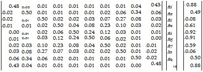
TABLE 11.3 Influence matrix for the airfoil shown in Fig. 11.27 using ten panels (a = 5°, constant-strength doublets only, with the Dirichlet boundary conditions)
|
 |
The solution is:
|
~ft? |
-0.6970030" |
|
|
ft2 |
-0.3259878 |
|
|
ft3 |
0.2767572 |
|
|
ft4 |
0.8576335 |
|
|
fti |
1.182451 |
|
|
ftb |
1.016438 |
|
|
ft7 |
0.5045773 |
|
|
ft8 |
-0.2092538 |
|
|
ft9 |
-0.8805848 |
|
|
ftw |
-1.270261 |
Mw — Mio Mi ~~ —0.5732538
Фм is equal to the local total potential jump ц across the solid surface. Thus, the local external tangential velocity above each collocation point can be calculated by differentiating the velocity potential along the tangential direction and Eq. (11.76) will have the form
Q, t = fli+A I* (1185)
The pressure coefficient and the fluid dynamic loads can be calculated now using the formulation of the previous section (Eqs. (11.77)-(11.80)).
Example 1 Lifting thick airfoil. This constant-strength doublet method is applied to the same problem of the previous section and the resulting pressure distribution with 10 and 90 panels is very close to the results presented in Fig. 11.27. It seems that this method is as effective as the combined source and doublet method and it does not have the matrix multiplication of the source matrix (less numerics). The influence coefficients for the N = 10 panel case are presented in Table 11.3 along with the solution vector. This information is presented since it was found that such data (as in Tables 11.2 and 11.3) is extremely useful in the early stages of code development and validation. Table
11.3 presents the doublet influence coefficients before and after the inclusion of the Kutta condition and also the magnitude of the solution vector цк, which is larger in this case than in the case shown in Table 11.2. This is a result of the unknown fik representing hete the total velocity potential whereas in the
|
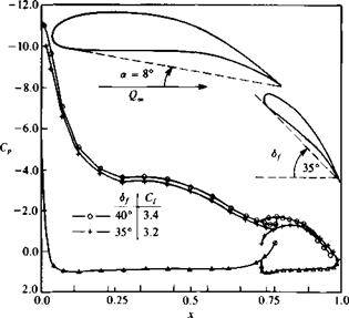
FIGURE 11.28 Effect of flap deflection on the chordwise pressure distribution of a two-element airfoil (triangles represent lower surface computational results for both flap angles). |
combined doublet/source case the doublet represents the perturbation potential only. Reference 9.2 claims that since the unknown цк are larger in the doublet-only solution, there is a numerical advantage (in terms of convergence for a large number of panels) for using the combined source/doublet method.
Example 2 Two-element airfoil. This method is applied to the two-element airfoil shown in Fig. 11.28. The effect of a 5° flap deflection on the chordwise pressure distribution is shown in the lower part of the figure. In general the effect of flap deflection is to increase the lift of the main planform more than the lift of the flap itself.
A sample student computer program for this method is presented in Appendix D, Program No. 7.


