Our heavyweight helicopter equal in the world does not have
In Rostov started production of the most load-lifting rotary-wing car The Russian holding «Helicopt[...]

Everything about aircrafts and helicopters. News and events in aviation worldwide. Civil, transportation, military helicopters and airplanes.

Everything about aircrafts and helicopters. News and events in aviation worldwide. Civil, transportation, military helicopters and airplanes.

Everything about aircrafts and helicopters. News and events in aviation worldwide. Civil, transportation, military helicopters and airplanes.

Everything about aircrafts and helicopters. News and events in aviation worldwide. Civil, transportation, military helicopters and airplanes.


Wait drag:
 |
In supersonic flow the disturbances are radiated away from the aircraft surface. Pressure balancing between aft and forward flow is impossible (Figure 26) or strongly limited for winged vehicles The result is wave drag, corresponding to the radiated energy (64).
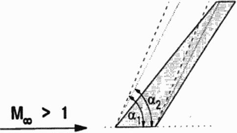
Figure 26 Wave Drag
All energy is radiated along Mach lines. Pressure (and temperature) changes along the aircraft, resulting in a crossing over of Mach lines at some distance When Mach lines intersect, conflicting information arrives at this point which will he bridged by a shock. Eventually all wave drag energy is captured by shock energy
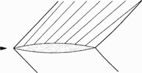
Circulation:
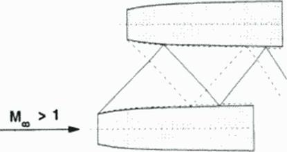
Disturbances can only propagate within the downstream Mach cone. This limits a build-up of circulation for finite wings (Figure 27). Leading edge flow can only influence the downstream part of the leading edge if the leading edge stays withtn the Mach cone (this is a so called subsonic leading edge). Information of the trailing edge can only reach other parts of the trailing edge to improve pressure recovery if the trailing edge is located within the Mach cone (subsonic trailing edge). The trailing edge can only improve a build-up of circulation if parts of the leading edge are within the trailing edge’s Mach cone; (his is only possible for low supersonic Mach numbers, high aspect ratio and high sweep angles.
|
|
Figure 27 Subsonic Leading and Trailing Kdges Kogan’s theorem:
Lift efficiency in subsonic flow is described by the downwind field behind the aircraft: si/e. strength and downwind distribution determine the induced drag (64|. Kogan (65J. [66J developed a similar theorem lor supersonic flow: Any point of the aircraft surface can only influence air in its downwind Mach conoid; any point on the aircraft surface can only he influenced by air in its upwind Mach conoid Kogan constructs the envelope of all downw ind Mach conoids originating at the aircraft leading edges, and all upwind Mach conoids originating at the aircraft trailing edges. The control surface defined by the intersection of those two envelopes contains all downwind information of the aircraft. Lift dependent drag of an aircraft is the smaller the larger this control surface area is, the smaller the mean downwind is and the less disturbed the downwind distribution is.
Interference drag:
Shocks generated on the surface of engine nacelles (and other interfering parts) arc radiated to neighbouring parts like the wing, to other nacelles or the fuselage, where they arc reflected (Figure 28). Reflection conditions and drag is strongly influenced by shock-boundary layer interference. This requires reliable nonlinear calculation methods including viscous effects. Wind tunnel simulation must be able to simulate the viscous effects of high flight Reynolds numbers
|
Figure 28 Shock Reflection on Neighbouring Kngines Inlet flow: |
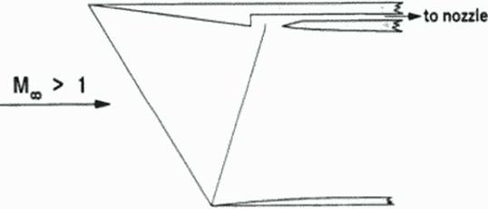
Jet engines work at purely subsonic speeds. The inlet of an SCT. therefore, has to decelerate incoming air from supersonic to subsonic velocities. This requires passing a shock system. To minimize shock losses, the air passes through several shocks (possibly including some iscntropic compression). Adequate mathematical models for the generation of shocks, control of shocks, shock position and shock reflection, including important viscous effects arc strongly nonlinear To enable stable flow conditions and engine operation, the inlet flow must be balanced with the nozzle flow; Concorde’s aerodynamically coupled nozzle and inlet control is still state of the art (Figure 29). Highly sophisticated numerical and w ind tunnel simulations are required and must be combined with the control system and engine operation
|
Figure 29 Inlet Flow. Concorde principle |
Hinge line shocks:
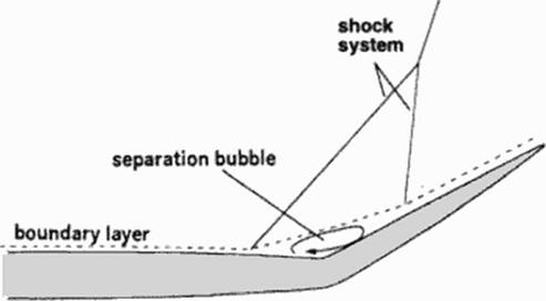
Al control surfaces, shocks at the hinge line region can provoke boundary layer separation bubbles strongly degrading flap efficiency and introducing vibrating airloads (Figure 30).
|
Figure 30 Shock-Boundary Layer Interference |