Gurney flaps
As well as being a great racing-car driver, Dan Gurney is also well-known for his technical innovations. His most widely emulated innovation is probably the now – obligatory practice of winning drivers spraying their supporters with champagne from vigorously shaken bottles. But it is for the Gurney flap that he is known in aerodynamics. This is a deceptively simple device consisting merely of a small plate fixed to and perpendicular to the trailing edge of a wing. It can be seen attached to the trailing edge of the multi-element rear wing in Figs 8.14 and 8.15.
Gurney first started fitting these ‘spoilers’ pointing upwards at the end of the rear deck of his Indy 500 cars in the late 1960s in order to enhance the generation of the downforce. The idea was completely contrary to the classic concepts of aerodynamics. Consequently, he was able to disguise his true motives very effectively by telling his competitors that the devices were intended to prevent cut hands when the cars were pushed out. So successful was this deception that some of his competitors attached the tabs projecting downwards in order to better protect the hands. Although this ‘improved’ arrangement undoubtedly impaired, rather than enhanced, the generation of a downforce, it was several years before they eventually realized the truth.
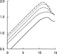
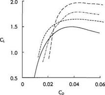
Gurney flaps became known in aerodynamics after Dan Gurney discussed his ideas with the aerodynamicist and wing designer, Bob Liebeck of Douglas Aircraft. They reasoned that if the tabs worked at the rear end of a car, they should be capable of enhancing the lift generated by conventional wings. This was confirmed experimentally by Liebeck.[60] The beneficial effects of a Gurney flap in generating an enhanced downforce is illustrated by the pressure distribution over the flap of the two-element aerofoil shown in Fig. 8.15. The direct effects of Gurney flaps of various heights on the lift and drag of wings were demonstrated by other experimental studies, see Fig. 8.16. It can be seen that the maximum lift rises as the height of the flap is increased from 0.005 to 0.02 chord. It is plain, though, that further improvement to aerodynamic performance diminishes rapidly with increased flap height. The drag polars plotted in Fig. 8.16b show that for a lift coefficient less than unity the drag is generally greater with a Gurney flap attached. They are really only an advantage for generating high lift.
|
a, degrees (a) |
|
(b) Fig. 8.16 The effects of Gurney flaps placed at the trailing edge of a NACA 4412 wing on the variation of lift and drag with angle of incidence. The flap height varies from 0.005 to 0.02 times the chord, c. —, baseline without flap;———- , 0.005c;———– , 0.01c;…….. , 0.015c;——— , 0.02c Source; Based on Fig. 7 of B. L Storms and C. S. Jang (1994) ‘Lift enhancement of an airfoil using a Gurney flap and vortex generators/ AIM J. of Aircraft, 31(3), 542-547 |
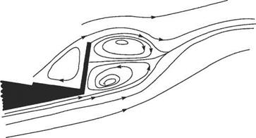
Why do Gurney flaps generate extra lift? The answer is to be found in the twin-vortex flow field depicted in Fig. 8.17. Something like this was hypothesized by Liebeck (1978).[61] However, it has only been confirmed comparatively recently by the detailed laser-Doppler measurements carried out at Southampton University (England)* of the flow fields created by Gurney flaps. As can be seen in Fig. 8.17, two contra-rotating vortices are created behind the flap. A trapped vortex is also included immediately ahead of the flap even though this is not shown clearly in the
|
Fig. 8.17 Flow pattern downstream of a Gurney flap Source: Based on figures in D. Jeffrey, X. Zhang and D. W. Hurst (2000) ‘Aerodynamics of Gurney flaps on a single-element high-lift wing’, AIM J. of Aircraft, 37(2), 295-301 |
measurements. This must be present, as was originally suggested by Liebeck. In an important respect, however, Fig. 8.17 is misleading. This is because it cannot depict the unsteady nature of the flow field. The vortices are, in fact, shed alternately in a similar fashion to the von Karman vortex street behind a circular cylinder (see Section 7.5). It can be also seen in Fig. 8.17 (showing the configuration for enhancing downforce) that the vortices behind the Gurney flap deflect the flow downstream upwards. In some respects the vortices have a similar circulation-enhancing effect as the downstream flap in a multi-element aerofoil (see Section 8.3.2).
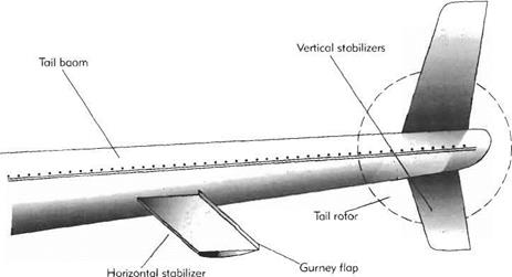
The principle of the Gurney flap was probably exploited in aeronautics almost by accident many years before its invention. Similar strips had been in use for many years, but were intended to reduce control-surface oscillations caused by patterns of flow separation changing unpredictably. It is also likely that the split and Zap flaps, shown in Fig. 8.8b and c, that date back to the early 1930s, produced similar flow fields to the Gurney flap. Nevertheless, it is certainly fair to claim that the Gurney flap is unique as the only aerodynamic innovation made in automobile engineering that has been transferred to aeronautical engineering. Today Gurney flaps are widely used to increase the effectiveness of the helicopter stabilizers.[62] They were first used in helicopters on the trailing edge of the tail on the Sikorsky S-76B because the first flight tests had revealed insufficient maximum (upwards) lift. This problem was overcome by fitting a Gurney flap to the inverted NACA 2412 aerofoil used for the horizontal tail. Similar circumstances led to the use of a Gurney flap on the horizontal stabilizer of the Bell JetRanger (Fig. 8.18.). Apparently, in this case the design engineers had difficulty estimating the required incidence of the stabilizer. Flight tests indicated that they had not guessed it quite correctly. This was remedied by adding a Gurney flap.
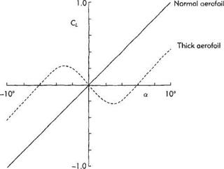
Another example is the double-sided Gurney flap installed on the trailing edge of the vertical stabilizer of the Eurocopter AS-355 TwinStar. This is used to cure a problem on thick surfaces with large trailing-edge angles. In such a case lift reversal
|
Fifl. 8.18 The Gurney flap installed on the horizontal stabilizer of a Bell 206 JetRanger |
can occur for small angles of attack, as shown in Fig. 8.19, thereby making the stabilizer a ‘destabilizer’! The explanation for this behaviour is that at small positive angle of attack, the boundary layer separates near to the trailing edge on the upper (suction) side of the aerofoil. On the lower side the boundary layer remains attached. Consequently the pressure is lower there than over the top surface. The addition of a double Gurney flap stabilizes the boundary-layer separation and eliminates the lift reversal.
|
Fig. 8.19 Lift reversal for thick aerofoils |


