Inviscid Hypersonic Flow: Numerical Solutions
The detached shock at the leading edge of a blunt body has a slowing effect for a vehicle re-entering to the earth atmosphere. The further away the shock from the body the less will be the heating effect at the stagnation region of the flow because of the high temperature rises after the strong shock. For this reason the location of the detached shock and the flow conditions behind the shock should be known for that high Mach number flows. Wind tunnel and shock tube testings are not capable of giving sufficient data at those high Mach numbers, therefore, the real flight recordings are used in studies when available. On the other hand, the inverse method which is based on determining the body shape and the flow around it for an assumed shock shape was an efficient method at late 1950s (Van Dyke 1958). For two dimensional and axisymmetric shocks a simplified inverse method is used to find the coordinates of the body surface (Maslen 1964). Let us choose the x coordinate parallel to the shock direction and y coordinate normal to that direction to form the local coordinates, Fig. 7.8, and non dimensionalize the flow parameters with free stream conditions and the shock radius. The velocity component u in the
|
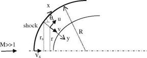
flow direction is much larger than the normal v component of the velocity. We can now write the equations
In nondimensional form in terms of f °f =(1 — y/R)rrpv, |f = rrpv
Continuity : 0[rrpu+0[(1 — y/R)rapv = 0, ! rr0y = —— (7.35a, b) ox oy of pu
0v. . 0v u2 1. . . 0p r0p u
y-momentum : u +(1 — y/R)v + + (1 — y/R) = 0, ! rr ffi
0x 0y R p 0y 0f R — y
(7.36a, b)
Here, r = 0 for two dimensional, and r = 1 for axially symmetric flows. If we nondimensionalize enthalpy with 1/2 U2, and show the stagnation streamline conditions with s the energy equation reads as: h + u2 + v2 = hsO + v2O. Then for the energy equation we write
![]()
u2 = hSo + vfo — h — v2
After the shock on a streamline we have p/pc = constant.
Simplifying Eq. 7.36a, b with the assumption of y/R ^ 1, the relation between the pressure and the stream function gives
![]() 0P ^ us 0f _ rrRs
0P ^ us 0f _ rrRs
Integration of Eq. 7.38 with respect to the stream function starting from the stagnation conditions fs we obtain
Neglecting the term (vO — v2) in energy equation the approximate form of Eq. 7.37 reads as
 |
||
In order to determine the r coordinate of the body surface, we can write: r = rs – y cos hs in terms of the tangent angle hs of the shock in Eq 7.35a, b to obtain
 |
 |
||
Integrating Eq. 7.42 with respect to the stream function gives
The second term at the right hand side of Eq. 7.43 is second order, therefore can be neglected to yield
Vs
![]()
![]() 1 ‘dv
1 ‘dv
rrs pu
V
Since we know the initial conditions, we can march one step to determine the new coordinate from the known stream function value as follows: (1) obtain the pressure p from Eq. 7.39, (2) find the density p on the streamline using isentropic relation, (3) The h enthalpy from equation of state, (4) the velocity component u from energy equation, and finally (5) y coordinate from Eq. 7.44. Now, let us apply the procedure described above to a spherical shock created by a body whose shape is to be determined.
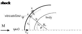 |
Example 7.2 For a spherical shock with radius of 1 immersed in M = oo and у = 1.4, find the flow conditions and the first body surface coordinate which has U = 30° at the center of the shock as shown in the figure below.
Solution: In order to simplify the solution, we assume that the streamline entering into the shock is oblique at with an angle 0s with existence of oblique shock relations. The pressure behind the shock then becomes: ps = 2/(у + 1) sin2 hs = 0.625, density: ps = 6, nondimensional speed in x: us = cos hs = cos (90° — 30°) = 0.5.
The stream function, since we have a uniform free stream before the shock, at s is for two dimensional flow: Ws = rs, and axially symmetric flow: Ws = r2/2. Hence: we find rs = cos ds = 0.5 and Ws = r2/2 = 0.125. Using Eq. 7.39 we can find the pressure at point b on the surface if we take the stream function value 0 as follows
Pb – Ps = Us(Wb – Ws)/R*rs = 0.5(0 – 0.125)/(1 x 0.5) then pb = 0.5.
The entropy remains the same on a streamline. This givespb/(qb)r = c = pso/(pso)r
The stagnation pressure is: pso = 2/(y + 1) = 0.8333 gives us the value of c. For W = 0 the density is pb = 4.166.
The enthalpy then becomes h = 2y/(y — 1)(p/p) = 0.840. Similarly, ho = 0.968. Using the energy equation we find the surface velocity as
ub = (ho – h)1/2 = 0.358.
Finally, we can find yb coordinate of point b that is the distance of point b to the shock, with three point accurate numerical integration as follows
This result show that the distance between the shock and the body at point b is the 13% of the shock surface. As a further practice take v = 0.0625 to find the flow conditions to determine approximate value of yb.
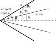
Example 7.3 Analyzing the conic shock about a slender cone at M = oo.
 M
M
—– ►
Solution: The conical shock shown in the figure above can be considered as an oblique shock with radius Rs = oo. With the method of Maslen the flow conditions behind the shock can be examined in a simple manner as follows:
The pressure p = Ps + Us(W — Ws)/(Rsrs) = Ps.
The density: p = p1/c [pJ(plJy)] = ps and the enthalpy: h = hs = 2y/(y — 1)(ps/ps) From the energy equation: u = us = (hso — h)1/2.
The distance between the shock and the surface: yb = Ws/(rspsus) = rs/(2pscos 0s)
The angle between the shock and the surface: tan (0s — 0c) = ybx = sin 0J
(2ps cos 0s), with which the cone angle 0c can be found.
Using the formulae above for у = 1.4, free Mach number = oo, and shock angle
15° for a conical axisymmetric shock the cone angle of the body is co = 13.7°.
We also find ps = 0.0558 and ps = 6.
Next, we are going to study and analyze the numerical solution of a shock created by the body of known shape at an angle of attack in hypersonic flow. The 1960s were the years of the space capsules which were sent for manned missions and came back safely to earth. The numerical solutions for the preliminary studies were performed for the Euler equations expressed in spherical coordinates with a method similar to that of Godunov (Bohachevski and Mates 1966). In the numerical solutions the finite difference method was used and the shock was captured within 4-5 discrete points across which the value of the density doubles itself. Shown in Fig. 7.9 is the numerically computed shock location obtained for a space capsule having a half cone angle of 35° with a spherical nose of radius of 4.74 m, immersed in a free stream Mach number of 29 with angle of attack of 20° at altitude of 66 km.
According to Fig. 7.9, the shock location is as close as 25 cm to the nose of the body, and at the maximum 45 cm away. The computed values of the density are at the most five times and at the least 2.5 times of the free stream density. For the specific heat ratio of у = 1.4 the Rankine-Hugoniot relations also give fivefold increase of the density after the shock. Another interesting result of this study shows that the streamline having the maximum entropy is the line crossing the shock and staying between the shock and the surface which is different from the stagnation line as shown Fig. 7.9. For a symmetric hypersonic flow, on the
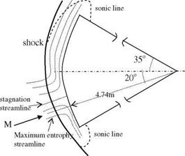 Fig. 7.9 Hypersonic flow
 rinted with permission of the American Institute of Aeronautics and Astronautics’’
other hand, the maximum entropy line coincides with the stagnation streamline (Anderson 1989).
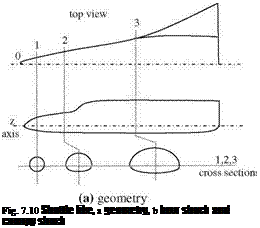
In the early 1970s, flow analysis around space shuttle type configurations started to appear in literature, by numerical solutions of Euler equations (Kutler et al. 1973). The aim of this type of detailed study was to numerically predict the hypersonic inviscid flow with multi shocks about the shuttle re-entering earth’s atmosphere at high angles of attack. These studies included calculating the effect of the interaction of the bow shock of the fuselage with the shocks created by the canopy and wings. Since the Rankine-Hugoniot relations are not capable of analyzing this type of complex interactions of shocks, shock capturing methods like MacCormack’s is resorted to march in the direction of the flow as a low memory requiring technique (Kutler and Lomax 1971). In their study, Kutler et al. cast the steady Euler equations in curvilinear coordinates in conservative form and marched in the flow direction step by step in accordance with the CFL (Courant Friedrichs Levy) using the finite difference method. Their solutions were second and third order accurate, and were compared for convergence concerning the resolution. The shuttle like geometry considered in their study had a spherical and a conical surface at the nose, and tangent to that two half expanding ellipses with their major axis coinciding; the flat bottom ellipse and the not so flat top ellipses as shown in Fig. 7.10.
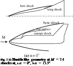
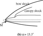
The numerical solution is first made for spherical-conical nose section shown in Fig. 7.10 as the region between the cross sections 0 and 1. The solution obtained at cross section 1 is given as the initial condition for the hyperbolic equation which is then solved by marching by MacCormack scheme until the desired cross section is reached. The numerical results for the position of shocks are provided in Fig. 7.11a, b at two different angles of attack for the free stream Mach number of M = 7.4.
 |
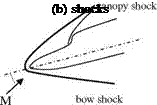 |
As seen in Fig. 7.11a, at zero angle of attack the bow shock interacts with the weaker canopy shock to generate a slip surface across which there is no pressure difference but velocity difference. The slip surface is only apparent for third order
 |
 |
accurate solution. In addition, the bow shock and the weaker wing shock interacts above the wing surface to make the bow shock almost tangent to the tail.
Shown in Fig. 7.11b is the flow field for 15.3° angle of attack at which the bow shock and the canopy shock do not interact and the bow shock is located way over the tail. At zero angle of attack, the surface pressure coefficient is eight times the free stream pressure right after the canopy shock.
In the beginning of 1990s, ESA (European Space Agency) also sponsored hypersonic flow studies past shuttle like double ellipsoid shapes solved with unsteady Euler (Molina and Huot 1992). This time the finite element method is employed in discretizing the domain of flow for which even viscous effects are also accounted for (Zienkiewicz and Taylor 2000). We can cast the time dependent Euler equations in appropriate form applicable to two dimensional hypersonic flows by defining the energy as e = h — p/p + 1/2(u2 + v2) to give continuity, energy and x and y momentum, respectively, as follows
P, t + (Pu),x +(PV),y = 0;
(p e),t + [(P e + p)u],x+[(P e + p)v],y = 0; (7.45a, b)
(Pu),t + (pu2 + p),x + (Puv),y = 0;
(pv)/ + (puv)x +(pv2 + p),y = 0 (7.46c, d)
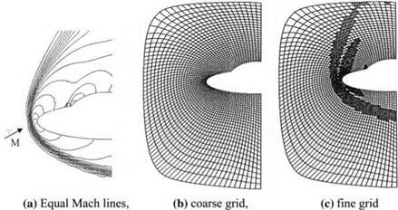
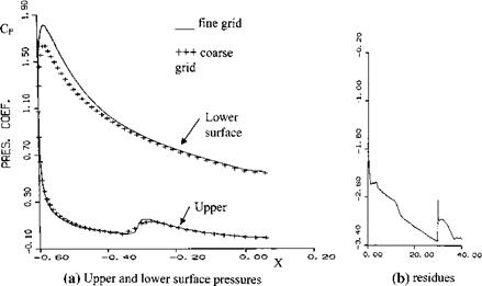
Shown in Fig. 7.12a is the flow field in terms of the Mach equal Mach lines around the double ellipse obtained by the finite element method at M = 8 and 30° angle of attack. The results are obtained by an adaptive scheme using the coarse grid first as shown in Fig. 7.12b. Afterwards, automatic remeshing is used at high gradient regions to get a finer grid as shown in Fig. 7.13c. In Fig. 7.13a, comparison of surface pressure coefficient is shown for the coarse and fine grids. Fine grid solution indicates that the suction is more at the lower surface and the
|
Fig. 7.12 At 30° angle of attack and M = 8, a equal Mach lines, b coarse, c fine grid |
canopy shock is stronger at the upper surface. Shown in Fig. 7.13b is the density residues before and after the adaptive mesh refinement.
The forward time and the finite element discretization of Eqs. 7.45a, b-7.46c, d in indicial notation become
J W(Ut+At – UAt)dQ = – At J (W + )Fi, idQ, i = 1,2 (7.47)
X Q
|
Fig. 7.13 Double ellipse solution a surface pressure coefficient, b residues |
Here, W is the weighing function, U = (p, pe, pu, pv)T is the unknown vector,
О ПГ О ПГ
F1 = (pu, (pe + p)u, pu + p, puv) and F2 = (pv, (pe + p)v, puv, pv + p) show the flux vector. In addition, At = 9F/ 9 U is the Jakobian of the fluxes and s AjW, j is the artificial viscosity. In terms of the element length h, local velocity magnitude |u|, and the local speed of sound c we can write s = 1/2 h/(|u| + c). On the other hand, Eq. 7.47 can not handle the numerical oscillations around the shock. Therefore, we add the term ^22=1(W,!U,!) into the integral at the right hand side. Here, k is proportional with the square of the element length h and gradient of the local velocity magnitude (see Problem 7.26).
So far, we have seen the hypersonic flow analysis based on the inviscid theory which does not take real gas effects into consideration. From now on in our analysis both the viscous effects and the disassociation caused by the heating of the air because of high speeds will be considered together with comparisons with the inviscid solutions.


