Multi-element aerofoils
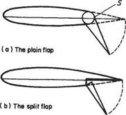
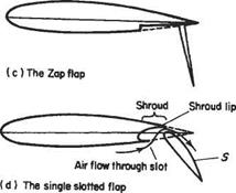
At the low speeds encountered during landing and take-off, lift needs to be greatly augmented and stall avoided. Lift augmentation is usually achieved by means of flaps[57] of various kinds – see Fig. 8.8. The plain flap shown in Fig. 8.8a increases the camber and angle of incidence; the Fowler flap (Fig. 8.8b) increases camber, angle of

|
|
|
|
|
|
|
|
|
|
|
|
|
|
|
|
|
|
|
|
|

![]()
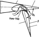
incidence and wing area; and the nose flap (Fig. 8.8g) increases camber. The flaps shown in Fig. 8.8 are relatively crude devices and are likely to lead to boundary-layer separation when deployed. Modern aircraft use combinations of these devices in the form of multi-element wings – Fig. 8.9. The slots between the elements of these wings effectively suppress the adverse effects of boundary-layer separation, providing that they are appropriately designed. Multi-element aerofoils are not a new idea. The basic concept dates back to the early days of aviation with the work of Handley Page in Britain and Lachmann in Germany. Nature also exploits the concept in the wings of birds. In many species a group of small feathers, attached to the thumb-bone and known as the alula, acts as a slat.
|
How do multi-element aerofoils greatly augment lift without suffering the adverse effects of boundary-layer separation? The conventional explanation is that, since a slot connects the high-pressure region on the lower surface of a wing to the relatively low-pressure region on the top surface, it therefore acts as a blowing type of boundary-layer control (see Section 8.4.2). This explanation is to be found in a large number of technical reports and textbooks, and as such is one of the most widespread misconceptions in aerodynamics. It can be traced back to no less an authority than Prandtl[58] who wrote:
The air coming out of a slot blows into the boundary layer on the top of the wing and imparts fresh momentum to the particles in it, which have been slowed down by the action of viscosity. Owing to this help the particles are able to reach the sharp rear edge without breaking away.
This conventional view of how slots work is mistaken for two reasons. Firstly, since the stagnation pressure in the air flowing over the lower surface of a wing is exactly the same as for that over the upper surface, the air passing through a slot cannot really be said to be high-energy air, nor can the slot act like a kind of nozzle. Secondly, the slat does not give the air in the slot a high velocity compared to that over the upper surface of the unmodified single-element wing. This is readily apparent from the accurate and comprehensive measurements of the flow field around a realistic multi-element aerofoil reported by Nakayama elaO In fact, as will be explained below, the slat and slot usually act to reduce the flow speed over the main aerofoil.
The flow field associated with a typical multi-element aerofoil is highly complex. Its boundary-layer system is illustrated schematically in Fig. 8.10 based on the measurements of Nakayama etal. It is noteworthy that the wake from the slot does not interact strongly with the boundary layer on the main aerofoil before reaching the trailing edge of the latter. The wake from the main aerofoil and boundary layer from the flap also remain separate entities. As might well be expected, given the complexity of the flow field, the true explanation of how multi-element aerofoils augment lift, while avoiding the detrimental effects of boundary-layer separation, is multifaceted. And, the beneficial aerodynamic action of a well-designed multi-element aerofoil is due to a number of different primary effects, that will be described in turn.*
|
Fig. 8.10 Typical boundary-layer behaviour for a three-element aerofoil |


