Off-the-surface recovery
What happens with a typical multi-element aerofoil, as shown in Figs 8.9 and 8.13, is that the boundary layer develops in the adverse pressure gradient of the slat,
|
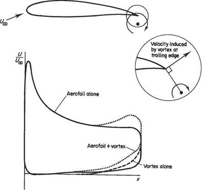
Fig. 8.12 Effect of a vane (modelled by a vortex) on the velocity distribution over the main wing |
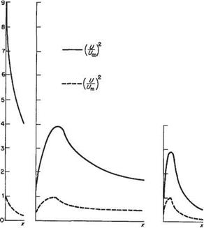
reaches the trailing edge in an unseparated state, and then leaves the trailing edge forming a wake. The slat wake continues to develop in the adverse pressure gradient over the main aerofoil; but for well-designed multi-element aerofoils the slot is sufficiently wide for the slat wake and main-aerofoil boundary layer to remain separate, likewise the wake of the main aerofoil and flap boundary layer. It is perfectly possible for the flow within the wakes to decelerate to such an extent in the downstream adverse pressure gradient that reversed flow occurs in the wake. This would give rise to stall, immediately destroying any beneficial effect. For well – designed cases it appears that the wake flows can withstand adverse pressure gradients to a far greater degree than attached boundary layers. Accordingly, flow reversal and wake breakdown are usually avoided. Consequently, for a multi-element aerofoil the total deceleration (or recovery, as it is often called) of the velocity along the edge of the boundary layer can take place in stages, as illustrated schematically in Fig. 8.13. In terms of the canonical pressure coefficient, UIUm takes approximately the same value at the trailing edge of each element and, moreover, the boundary layer is on the verge of separation at the trailing edge of each element. (In fact, owing to the vane effect, described above, the value of (U/Um^ for the flap will be lower than that for the main aerofoil.) It is then evident that the overall reduction in (UjU^) from (f7m/I/0C)s]ilt to ( Ute/I7oo)fiap will be very much greater than the overall reduction for a single-element aerofoil. In this way the multi-element aerofoil can withstand a
|
|
|
Fig. 8.13 Typical distributions of velocity ratio over the elements of a three-element aerofoil |
very much greater overall velocity ratio or pressure difference than a comparable single-element aerofoil.


