Power and Thrust Coefficients for a Wind Turbine
Using Eq. 13.7 with Eq. 13.3 and expanding out gives
P = 2pA (Vqc — Vi)2 Vi. (13.9)
We now define a power coefficient (different to that used for a helicopter) in terms of the wind speed as a reference such that
so that
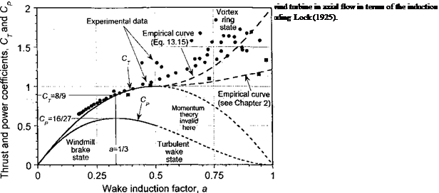
The relationship in Eq. 13.11 is shown graphically in Fig. 13.4 and can strictly be valid only for 0 < a < 1/2 to avoid violating the assumed flow model by having the possibility of both downstream and upstream flow directions. We can also find the thrust coefficient acting on the turbine. Using Eq. 13.3 then the thrust is
![]() T — mw = pA(V, oo – vi)w = 2pA(Voo – vfivi
T — mw = pA(V, oo – vi)w = 2pA(Voo – vfivi
Now, defining the corresponding thrust coefficient as
![]()
![]()
 (13.13)
 |
|
means that
which is also shown in Fig. 13.4 but again the result is valid only for 0 < a < 1/2. Notice further that Cp = (1 — a)Cp in this case. Also shown in Fig. 13.4 is an empirical result for Cp in the range 1/2 < a < 1 (i. e., turbulent wake region) often attributed to the analysis of Glauert (1926), but see also Lock et al. (1925). Another fit based on the results described in Section 2.13.3 and shown in Fig. 2.18 is also given. Eggleston & Stoddard (1987) suggest
replacing Eq. 13.14 by Cj = 4a 1 — a for a > 0.5 but this is obviously incorrect. A more satisfying approximation to use is
CT =4(a-)a+2, (13.15) although various other empirical equations seem to have been used [see Burton et al. (2001) and Buhl (2004)]. While this and other such equations mimic the results that have been measured (or estimated from measurements) in this regime, they are not based on any physical rationalization of the flow state associated with the increased thrust in the turbulent wake or vortex ring state (VRS). Some other results in this region can be deduced from the complete induced velocity curve shown previously in Fig. 2.18, where it will be apparent that Ct and a in the wind turbine case are related to the climb and induced velocity of the rotor using

![]()
![]()
 |
(13.16)
Therefore, the Ct versus a curve given by Eq. 13.15 is simply an alternative empirical realization of the portion of the complete induced velocity curve that cannot be defined theoretically using momentum theory.


