Representative Power Curve for a Wind Hirbine
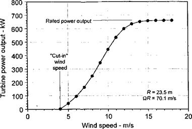
The amount of power produced by a wind turbine as a function of wind speed is obviously of primary importance for design. A representative power curve is shown in Fig. 13.5 for a large 47 m (154.2 ft) diameter turbine that has a rated electrical power output of 0.66 MW (885 hp) at 28.5 rpm. First, notice that there is a “cut-in” wind speed below which the turbine produces no power. This is, in part, because of the need to overcome mechanical friction in the system, which will require some minimum wind speed before the turbine starts to produce useful power. Also, there are aerodynamic losses to overcome that have their origin in viscous effects. This is because the turbine first starts to operate at high angles of attack with stall on the blades and the net wake flow is also in the turbulent wake state where there are rotational energy losses in the flow. Therefore, a minimum wind speed is required to overcome these losses. Second, notice from Fig. 13.5 that, after power is being produced, the output increases rapidly and is essentially proportional to V^, as would be expected based on Eq. 13.1.
Third, as a certain wind speed is reached, it will be noted that the power output levels out and approaches a limit known as the rated power output. This power limiting is done using one of a variety of strategies to ensure that the turbine does not absorb more power from the wind than could be absorbed by the electrical generator operating at its maximum continuous rating. One strategy is to use blade pitch control, where the blade pitch angle is adjusted automatically to match the power output to the wind speed. At higher wind speeds, the blades can be feathered to stall the blades and thus to prevent a runaway condition. At very high wind speeds or in storms, the blades can be feathered into a parked position, slowing or stopping the turbine and cutting its power output completely. Alternatively a mechanical or aerodynamic brake (such as spoilers) can be used instead of pitch regulation. For small wind turbines another technique is used to turn the rotor out of the wind to cut its energy production. This is known as furling – see Muljadi et al. (1998) and Eggers et al. (2000) for a discussion of furling and approaches to its aerodynamic modeling.
The power curve for a wind turbine may be plotted as a power coefficient CP versus wind speed or more usually as CP versus tip-speed ratio (TSR). For a wind turbine the tip speed ratio XTSR is defined as
This parameter is essentially the reciprocal of the rotor advance ratio used in helicopter work and it is important that the two parameters are not confused. For the results shown
|
Figure 13.5 Power output from a representative constant tip-speed wind turbine as a function of wind speed. |
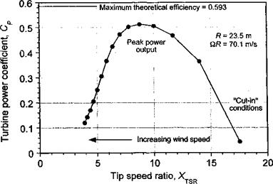
in Fig. 13.5 the corresponding airpower Cp versus XTSR curve is shown in Fig. 13.6 when allowing for a 90% electrical-mechanical conversion efficiency in the measurements. Notice also that the aerodynamic efficiency reaches a peak of almost 85% of the theoretical maximum when the turbine is operating at its rated speed. This suggests a very well-designed turbine in this case, but will generally be typical of large modem designs.
However, it will be apparent from Fig. 13.6 that peak efficiency for a constant speed (rpm) turbine is obtained only over a very narrow range of wind speeds (i. e., at a single TSR). This means that, conversely, this type of wind turbine does not operate at peak aerodynamic
|
Figure 13.6 Representative power coefficient versus tip-speed ratio curve for a constant speed (rpm) horizontal axis wind turbine. |
|
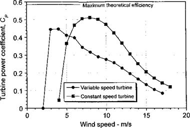
Figure 13.7 Representative power coefficient versus wind speed curves for constant speed and variable speed types of horizontal axis wind turbines. |
efficiency over a very wide range of wind speeds.[46] This is a disadvantage of the constant speed type of wind turbine, despite its mechanical simplicity. However, not all wind turbines are designed to operate at constant tip speed or with constant blade pitch. Smaller wind turbines are often designed to run over a range of tip speeds and can exhibit more efficient energy extraction at lower wind speeds, as shown in Fig. 13.7. The disadvantage, however, is that the aerodynamic efficiency of a variable speed turbine drops off quickly at higher wind speeds. Yet at high wind speeds the loss of efficiency also serves to regulate the turbine’s power output. The most common type of wind turbine in use today is the large variable speed turbine, where the power efficiency is fixed below the rated wind speed by electrically controlling the generator torque.


