STABILITY OF STREAMLINE BODIES
Typical streamline bodies are unstable. Devices such as missiles, bombs, airships and fuselages can be stabilized by adding fins to their rear end.
Static Stability. As stated in context with equation 22 there is a range of the angle of attack (or yaw) around zero, where lift or lateral force and moments vary in linear proportion, so that dC^/dC*. = constant. This derivative represents the minimum of the static stability (33). When using a moment coefficient referred to the bodies length (subscript^) the neutral point (where the moment is zero, and/or about which the static stability parameter may be constant) is located at
Д X/-C = dCw/dCL

![]()
![]()
![]()


 where A x = distance measured from the center of gravity or the reference point about which the moment is tested, positive when downstream. Since stability of bare streamline bodies is usually “negative”, the neutral point is forward accordingly. In fact, it may be located far ahead of the body’s nose, such as x = —^, for example.
The Cones as in figure 1, have a fairly constant center of pressure, equal to neutral point (or aerodynamic center), located between 64 and 65% of their length. Cones thus behave in the same manner as slender delta wings. Placing the CG slightly ahead of 64% of the length, conical bodies could thus provide stable lifting “vehicles”. The circular type in figure 24 has a maximum L/D = 2.4, at Cl 0 = 0.4, id est based on base area. The L/D ratio could be improved by giving the cone a flat (elliptical) cross-section shape, of the type as included in figure 2, for example.
|
Figure 30. Stability (position of neutral point) of the essentially cylindrical “scout” rocket vehicle (38,a) for three different conditions of the tail end. |
Cylindrical bodies with some type of “streamline” nose, could be expected to have their neutral point within the length of the nose; roughly as follows:
at 2/3 of nose length, for conical shape at 1/2 of length, for ogive (as in figure 15)
Because of the “viscous” type of lift developing in the cylindrical afterbody (see equation 8) the neutral point may be further aft, however. For example in the shape at the bottom of figure 14, the point is at or slightly behind the juncture between nose and cylinder.
A Flared Tail End as in the second configuration in figure 30, is theoretically expected to provide a stabilizing force the magnitude of which corresponds to equations 1 and 3,
dCLd /doc = (SB /Sd -1) 0.0274 (26)
where “B” indicates the base area. The tested differential ACNo = 0.02 agrees with this equation sufficiently well. Moment and neutral point can be calculated as they were tested.
= 6.7 d
Cn = "^"/qd2^ about o.5 point
Су = Y/qdC p = angle of aideslip
Figure 31. Longitudinal characteristics of three streamline bodies of revolution (9,h) differing in the shape of fore-and afterbody.
Boat Tail. As soon as the afterbody is made tapering, it begins to produce a negative lift force, thus making the moment more unstable (tail down, nose up) and causing the neutral point to move forward. Figure 15 is an example, where the addition of a boat tail results in a neutral point location ahead of the body’s nose. The shape with the cylindrical afterbody in figure 26, will be stable if placing the CG ahead of x = 0.2. Boat-tailing (reducing the width of the afterbody) reduces stability. In fact, stability of the second shape in the illustration (still having a blunt base) is almost as poor as that of any pointed tail shape (such as an airship hull, for example). This result is confirmed in figure 31 where characteristics of three same-size bodies are listed, differing in shape. The blunt-based body has nearly the same derivatives as the slender double-pointed type.
Streamline Bodies. Although the results in figure 31 may quantitatively be deficient (23) they nevertheless demonstrate how stability deteriorates when “streamlining” the shape:
When reducing the afterbody to a point, the neutral
point moves forward.
when giving the forebody a fuller shape, the point moves still further forward.
As a consequence, “perfect” streamline shapes such as in figures 32, 33, 34 have neutral points up to about once their length ahead of the nose.
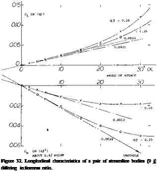
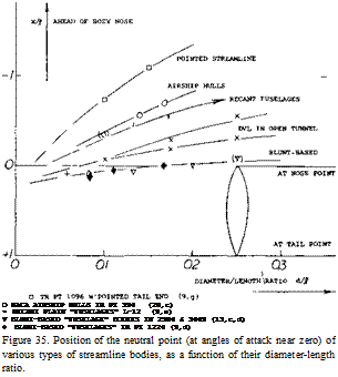
Thickness Ratio. Characteristics of two streamline bodies differing in thickness ratio, are presented in figure 32. While, this time based on area (b.|), the lift-curve slopes are roughly the same, the fatter body is much more unstable than the thin one. Neutral points of various types of bodies are plotted in figure 35, evaluated from tested pitch and/or yaw derivatives show:
a) round streamline bodies with a tapering afterbody ending in a point are most unstable.
b) airship hulls (bare, without fins, but with polygonal edges) still have a position of the neutral point more than half of their length ahead.
c) sufficiently blunt-based “fuselage” shapes are the least unstable; their neutral point may be at their nose point.
The mechanism of negative lift in the afterbody (see figure 1) evidently deteriorates as the boundary layer grows with the length ratio ijd. At d/Л —0, we may speculate that the center of whatever linear lift component might still exist, is somewhere within the nose part.
 d = o.10j[
![]()

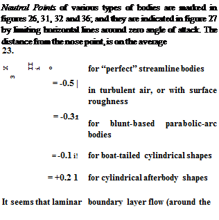 |
nose) results in more unstable characteristics, while surface roughness is stabilizing. Stability about a given point such as the center of gravity, corresponds to
dC^ /dC. L =(хг1/^-(х9Д) (27)
where Xg = downstream of the CG from the nose of the body. A body is stable when the derivative is positive, id est when the CG is ahead of the neutral point.
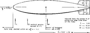
Wedge Shape. Without fins, streamline bodies are hopelessly unstable. For example, the derivative of the bare and smooth airship hull in figure 37, about the CG at x = 0.45.|, is dC^jldC^ = -1.55, which means that the neutral point is 1.1 body lengths ahead of the bow. From efforts to improve the hull shape, the configuration as in figure 38 was investigated and indicated:
a) When giving the tail end a wedge shape, with a vertical trailing edge, both the basic linear and the “second” non-linear lateral force components are increased..
b) Analysis confirms that the additional forces originate in the rear end, approximately at a “center” as indicated in the drawing.
c) As a consequence of (a) and (b) bodies with a flat tail end are less unstable. When making the trailing edge, h = d, the hull might obtain a stability similar to that of ogive-cylinder combinations.
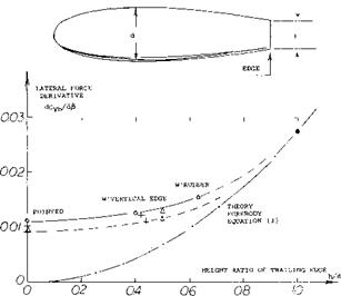
 The yaw-moment derivative of the airship hull and those of a few other “fuselage” bodies having a wedge-like afterbody shape, are plotted in figure 39. The results correlate with equation 3. A modification similar to that in figure 37, is shown in figure 38 of Chapter XIII. In that case, the neutral point is located ahead of the body’s nose, at
|
|
|
|
|
![]()
![]()


![]()
![]()
![]() X = 804 ft AT AVA (34. a!
X = 804 ft AT AVA (34. a!
= 245 m
V = 80 MPH V = 0.5 b2
J = 6 d Rj = 5 (10)”
FORCES SHOWN ARE AT at = 4°
a) WITHOUT FINS
b) WITH FINS 0
c) WITH ELEVATORS AT 20
COEFFICIENTS BASED ON d2 Area, for EXAMPLW IN (c) CN = 0.23
Cx = °-07
![]()
![]()
![]()
![]()
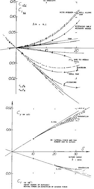
Figure 37. Longitudinal stability characteristics, with and without fins, of LZ-128 “Graf Zeppelin” airship (34,a).
Dorsal Fins are usually meant to be comparatively narrow surfaces attached to the tail end (or possibly the front end) of fuselages. Forces and moments of a plain “fuselage” model are shown in figure 40, without and with such fins (strips of metal) attached to the afterbody. With these strips there is a modest influence upon lift and moment near zero angle of attack. Also the non-linear lift or normal-force component is considerably increased along with improved stability at the higher angles of attack.
In conclusion, “dorsal” strips are primarily effective at higher angles of attack. The normal-force increment is roughly Д Cw — sin2 oc. In figure 40, the cross flow coefficient of the part of the afterbody “covered” by the fins (on projected lateral area SF ) is in the order of
Cc =(dCM/d(sin2cK))(b^/SF)=3
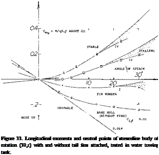
Tail Fins. A body with the round and full forebody such as shown in figure 30 is the most unstable kind. There is evidently no “support” in the afterbody; and the forebody force is located comparatively far ahead. The only aerodynamic means of stabilizing such streamline shapes, are fins attached to their tail end. The longitudinal (pitch or yaw) moment of a streamline body (similar to the hull of an airship or a submarine) is plotted in figure 33. Static stability about the center of buoyancy or gravity, is only obtained after adding the largest fin shown (number IV). The stabilizing moment of the tail fins (subscript “T”) corresponds to
The lift curve slope might be predicted for two extreme cases:
a) For small aspect ratios, equation 3 suggests a dCfb /doC = 0.0274. The contribution of tail number IV is some 10% larger than this, possibly because of favorable 2-alpha type body interference.
b) In the range of larger fin aspect ratios, it can be assumed that the effective ratio is Vl the geometrical one (36). Using equations of Chapter III, the lift-curve slope can thus be obtained. The contribution of tail number I (with A = 4.4) agrees well with this type of estimate.
Fin Size. When adding fins to a streamline body, the neutral point moves aft, say from хЦ = -1 (ahead of the nose) possibly to хЦ = +0.5 (half way between nose and tail point). The difference Д x/f = 1.5 is the length stabilized by means of the fins. In figure 33, it is seen how stability (position of the neutral point) varies as the chord length of the fins is increased. The configurations shown in figure 34 demonstrate how stability increases with the span of the fins. It may be speculated that the stabilizing forces originating in the fins grow in proportion to their chord length and to the square of their span. Neutral – point positions were, therefore, plotted in figure 41 as a function of the tail-size parameter (b/d) (сЦ). The functions thus obtained can empirically be interpolated by
А хЦ = (dC^ /dCL ) = 2.5 V(b/d)2 (с/Д)" (28)
|
Figure 39. Lateral force derivatives of streamline bodies, as a function of the height of the trailing edge (if any). |
(32) ARC, Characteristics of airships, pitching and turning:
a) Pannell, R-32 Turning, RM 668 & 812 (1921).
b) Simons, Stability and Turning, RM 713 (1919).
c) Jones, Stability, RM 751 & 799 (1922).
d) Jones, Equilibrium in Turns, RM 716,749,781,78 2 (1922).
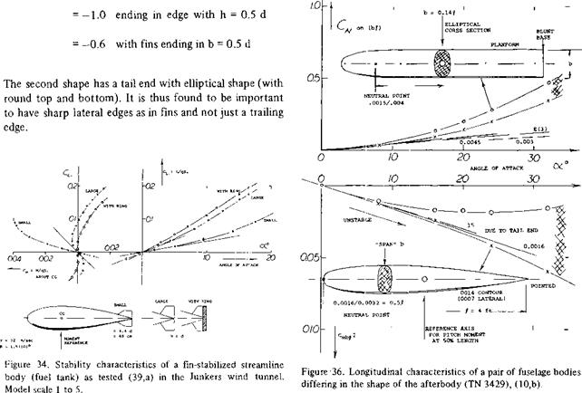
Ring Surface. Lift and moment (about the CG as indicated) of a streamline fuel tank (to be dropped when necessary) are presented in figure 34. The “small” set of fins is evidently not sufficient to stablize the body. Neutral stability is only obtained after adding a small “ring” to the larger set of fins. The model of a 1000 kg bomb was tested with two different tail surface configurations. As shown in figure 42, addition of a ring around the four fins, increases stability. The neutral point is moved aft on account of the ring by Л x = 0.16_f. It can be assumed that the increment of the stabilizing forces in the tail surfaces are obtained on three counts:
1) the ring serves as an end plate, thus increasing the effectiveness of the fins;
2) the ring surface develops stabilizing forces of its own (see equation 20);
3) the ring reaches out into the flow outside the body’s boundary layer (wake).
In the configurations as in figures 34 and 42, the stabilized length is increased by the addition of a ring, roughly by 10 and 20%, respectively. This small change can make the difference between stable and unstable configuration.
Airship. Stability characteristics of an airship are shown in figure 37. Without fins, the slope near zero angle of attack (or sideslip) dC^ /dCL = —1.4 means that the neutral point is roughly one length ahead of the nose. After adding the set of fins, that point is brought back as indicated, roughly half way between nose and the center of buoyancy The airship is not stable in this condition. The speed of these vehicles is evidently low in comparison to their mass; which means that their Froude number is comparatively low. As a consequence, the deviation from their direction of motion takes place at such a slow rate that correction by manual or automatic control (rudder and/or elevator) deflection) can easily be accomplished. As shown in 30,f one particular airship needs alternating rudder deflections of plus/minus 4° to keep it on course. Although it would be possible to make the airship in figure 37, stable by increasing the size of the fins, it was evidently concluded that this would not “pay”. Larger fms would add to drag and weight. As we will see later, the maneuverability (turning) would also be reduced when increasing stability.
(33) For a discussion of the dynamic stability of airships see (30,f) and (32,e). for example.
(34) Investigations in AVA wind tunnel:
a) Kohler, “Zeppelin” Airships, Ringbuch D’Lufo Rpt IA15 (1940).
b) Kohler, Airplane Skis, Luftwissen 1937 p 6.
Tail Fins. When attaching fins to the stern of the airship hull as in figure 21, they first produce some circulation – type lift. The linear normal-force slope is doubled; dСд, ь /doc = 0.003. Based on various areas, the increment (due to fins) has the derivative:
|
A( dCN/doc) =0.003 |
on lateral hull area (d ) |
|
= 0.024 |
on hull diameter area d |
|
= 0.055 |
on exposed fin area |
|
= 0.026 |
on fin plus |
|
“ с о vered” |
|
|
area |
The most reasonable definition is the last one, on “total” fin area, including the part of the hull between them. The slope somehow corresponds to the geometric aspect ratio Ар = 0.7. There are interference effects involved, however:
a) At the sides of the hull, the angle of attack of the fins is possibly doubled, on account of “2 alpha” cross flow.
b) As explained for horizontal tail surfaces, in Chapter XI, the boundary layer (wake) developing along the hull interferes with the circulation around the fin plus stern configuration.
The stabilizing moment due to the lifting forces in the stern, corresponds to
dC^/doC – (dC^ /dec )C/T/T) (29)
where ” moment arm of the “tail” to the axis of reference. Solving the results as in figure 21 for that arm, it is found that the location of the stabilizing tail force is at
x/* = (dC^/doOM (dCN)/doc) =
0.0013/0.0015 = 0.89
which is as expected, somewhat forward within the area of the, and covered by the fins.
(35) Dorsal and other fins on fuselages:
a) see Bates in reference (10,b).
b) Hoggard, Around Plain Body, TN 785 (1940).
c) Recant, Fighter Model, NACA W’Rpt L-779 (1943).
Stability. The center of gravity of an airship is or has to be identical with that of the buoyancy. In the example as in figure 21, the center is at 46% of the length. The stabilizing effect of the fins at the end of the hull corresponds to a moment arm Jp Ц= 0.47. When shifting the axis of reference to the nose point, dC^/d/} is just about zero. For practical purposes, this means that the airship would be stable if it would pitch about the axis through the nose point. Stability (33) improves, however, when reaching higher angles of a ttack, where the fins provide a “second” and non-linear normal-force component. Extrapolating corresponding to equation 14 the ACN due to fins as in
The last definition yields a very reasonable value for the fin configuration considered.


