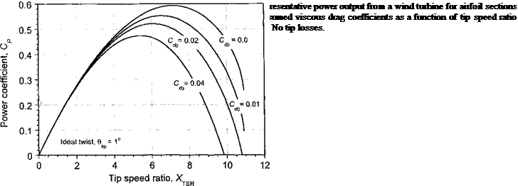
Tip-Loss Effects
The induced nature of the vortical wake and its effects on the spanwise loading on the blades can be approximated using Prandtl’s tip-loss function as shown previously for the helicopter rotor in Section 3.3.10. Because the basis of the BEMT is a strictly “2-D” theory, 3-D effects such as the physical roll-off in the lift as the blade tip is approached must be treated using corrections, although the better approach is to use lifting-line and vortex theory (see Section 13.11). The Prandtl correction can account approximately for a finite number of blades and also for variations of blade planform and twist through the effect on the inflow angle.
Prandtl’s “tip-loss” result can be expressed in terms of a correction factor F to the change in momentum over the annulus of the disk in Eq. 13.55 such that
dCj = 8F(1 — a)ar dr where F = (— j arccos (exp(—/)), (13.55) where the exponent / is given in terms of the number of blades and the radial position of the blade element r by
![]() z r<p / z л — a J
z r<p / z л — a J
If root losses are also to be modeled, then it will be apparent that the corresponding equation for / is
![]()
 |
(13.57)
where ro represents a root cut-out distance, which represents the lack of aerodynamic lift – producing surfaces close to the hub. With the incorporation of tip – and root-loss effects into
the BEMT the induction factor becomes
![]() O^TSR Q, , 12 _ aXTSRClg(XTSRer + l)
O^TSR Q, , 12 _ aXTSRClg(XTSRer + l)
16 F + 2J 8 F
![]()
![]() (13.58)
(13.58)
Because F is not known a priori, in the first instance Eq. 13.58 is calculated from the inflow angle (or induction factor) after assuming that F = 1. Repeating the calculation for a and F using Eqs. 13.58 and 13.55 shows rapid convergence, normally within 3 to 10 iterations.
The numerical process for including the Prandtl tip-loss function will fail, however, if the square-root term in Eq. 13.58 produces an imaginary result, that is, if
This means that the inclusion of the Prandtl tip-loss factor can limit the range of wind speeds and operating conditions over which numerical solutions can be found using the BEMT simply because the governing equation breaks down numerically as a becomes greater than 0.5. This problem can be circumvented if the relationship between induction ratio and thrust is represented using the empirical branch of the curve for a > 0.5, say when using Eq. 13.15 because of its simple analytic form (see also Fig. 13.4). While this assumes that the induction ratio is constant (or almost so) over the disk, for any values of a approaching 0.5 this means that multiple flow directions are possible and so there is a decreasing validity of the momentum theory, in general. In this case, the fundamental equation for a must be rederived, such as using Eq. 13.15. In this case, equating the momentum and blade element results gives
(8(a – l)a + 4) F = oX^Qr = (Хта0г + (1 – o)), (13.60)
which after manipulation can be expressed in the analytic form
а2 + – Л a + (1 – + ])) = 0. (13.61)
8 F ) 2 8 F )
This has the solution
iy /1 oXTSIQ.(X„„er+l)
a(.r, XTsl, F) = ^-1^–J —————- — ————
_ /O^tsrQ, _ i
A 16F ?/’
—— — /
This modified equation is valid for the extended range 0.5 < a < 1.0, where it should be understood that it is based on an underlying empirical assumption and an extension of the Prandtl tip-losses concept to flow conditions where the assumptions inherent in the BEMT become increasingly questionable. Nevertheless, in light of the results obtained (see next section) its use seems appropriate for engineering purposes because it allows the BEMT to be used for wind turbine analysis over a wider range of practical operating conditions.
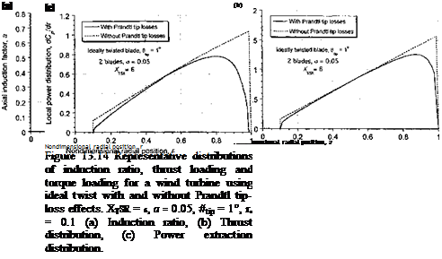
Representative calculations of the spanwise distribution of induction ratio, thrust distribution and distribution of power extraction on a wind turbine as predicted using the BEMT
 |
are plotted in Fig. 13.14. The results are shown with and without the Prandtl tip and root losses and for a case where locally near the tip a is greater than 0.5. Notice that the tip – (and root-) loss function serves to increase the induction ratio over much of the blade, in part because the blade in this case is not of particularly high aspect ratio (R jc = 10). These “tip losses” decrease the thrust on the turbine and also decrease its power output. Because most of the net airpower generated by the turbine comes from stations toward the blade tip, it is apparent from Fig. 13.14(c) that tip effects are really a very substantial source of aerodynamic losses and modeling the effects accurately is of fundamental importance. The use of vortex theory, such as with the use of a lifting line and a trailed vortex wake, is a more physically pleasing way of modeling such losses (see Section 13.11).


