Coordinate Transformation Matrix
Coordinate systems are related by coordinate transformation matrices that relabel the coordinates of a tensor. We will dissect them and examine their elements more closely. Two representations will help us to better understand their composition.
3.2.1.1 Base vector representation. Introduce x, a first-order tensor, and any two allowable coordinate systems ]A, R with their transformation matrix [Твл. From the definition of a first-order tensor, Eq. (2.3), we have
![]() [x]B = [T ]BA[x]A
[x]B = [T ]BA[x]A
Furthermore, introduce the triad ai, аг, and аз (see Fig. 3.8), associated with the frame A. Decompose x into the vectors of the triad
x = xfai + хАаг + хАаз
x/’. / = 1,2, 3 are the coordinates, and х/’а,-, і = 1, 2, 3 are the components of the vector. Now express x in ]s coordinates:
![]()
 |
[х]в = х?[аі]в +х£шв +х*[а3]в
This equation can be written as a scalar product
(3.3)
If we select ]A as the preferred from all of the associated coordinates systems, then the vector x is coordinated directly as
 MA =
MA =
and therefore Eq. (3.3) becomes
WB = [[fli]B ШВ [a3]B][x]A
Comparing this equation with Eq. (3.1), we find a representation for the coordinate transformation matrix
[T]BA = [[a i]B [n2]B [я3]в] (3.4)
Its columns consist of the frame A base vectors, coordinated in ]B, and predicated on using the preferred coordinate system for frame A.
We can reverse the derivation and decompose vector x into the triad b,b2, and b2 of frame В
x = xBb + xBb2 + xBb2 and coordinate it in the ]A system
[x]A = xflbtf +x2>2]A +xB[b3]A = [Ybrt [b2]A [Ьъ]А}[х]в
Solving for [x]B and comparing with Eq. (3.1) yields another representation for the transformation matrix: [bi]A
![]()
![]() [b2]A
[b2]A
[Ьз1А
The rows are the base vectors of frame В transposed as row vectors and coordinated in the ]A system. Both presentations can be summarized in the following schematic with tij the elements of [T]BA
 [bi]A
[bi]A
mA
[b3]A
In summary, the coordinate transformation matrix consists of base vectors coordinated in their preferred coordinate systems. Frequently, I will abbreviate the expression “coordinate transformation matrix” simply by TM.
3.2.1.2 Direction cosine transformation matrix. There is another interpretation of the elements of TM. If we write out the coordinates of Eq. (3.4),
|
|
we can interpret each element as the cosine of the angle between two base vectors. The first subscript indicates the b triad and the second subscript the a triad. Let us check it out using the a® term (see Fig. 3.9). To calculate the cosine of the angle between the base vectors b and a, take their scalar product and express them in the ]® coordinate system
|
|
cosZ(ft],ai) = [51]s[a1]B = [1 0 0] a® = a®
Indeed, a® is the cosine of the angle between the two base vectors. You can also start with Eq. (3.5) and reach the same conclusion. In general, for any b, and we can calculate the cosine of the angle according to the formula
cos l(bi, ak) = аЦ = tik’, г = 1,2,3; к = 1, 2, 3 (3.6)
Because the elements are the cosines between two directions, the TM is also called the direction cosine matrix, a term quite frequently assigned to the TM of the body wrt the geographic coordinates.
|
а
|
Example 3.1 Tracking Coordinate System
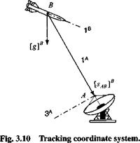
Problem. Figure 3.10 shows a missile В being tracked by a search radar A. The onboard computer must determine the tracking radar’s coordinate system and the TM [T]BA of the missile’s coordinates wrt those of the tracking radar. Available are the gravity vector [g]s and the displacement vector of the radar wrt the missile both measured in body coordinates. Some additional information is known about the coordinate system of the tracking radar. Its 1A axis is parallel and opposite of the displacement vector and the 2A axis is horizontal (into the page).
What are the equations that the missile processor has to execute?
Solution. We start by formulating the radar’s base vectors in missile axes. Then it is just a matter of using Eq. (3.4) to calculate the transformation matrix. The first base vector is the unit vector of the negative displacement vector
![]()
 |
I I
The second base vector is obtained from the vector product
в = [SAB]B[g]B
|[ЗДВЫВ1
where the upper case [5дв]в indicates the skew-symmetric matrix of the lower case displacement vector sAbr. The third base vector completes the triad
We program the following matrix with three columns for the missile computer:
[Jab]b [£ав]ВЫВ
клві |[ЗДВЫВ1 1^В||[ЗДВЫВ1
As the missile continues on its trajectory, the and [g]s coordinates change
(why does [g]s also change?), and the calculations have to be continually updated.
3.2.1.3 Properties of transformation matrices. As we model and simulate aerospace vehicles, we will be manipulating many coordinate transformations. It is, therefore, important for you to have a good understanding of their properties.
Property 1
Transformation matrices are orthogonal.
Proof: Use the fact that the scalar product is the same in two coordinate systems. Introduce any vector* and any two allowable coordinate systems ]A andH. Formulate the scalar product in both coordinate systems and then use Eq. (3.1):
mA[x]A = mB[xf = mAmBA[T]BA[x]A
The outer equations form
[x]A([T]BA[T]BA – [£])[x]A = 0 Because [x]A is arbitrary,
[T]ba[T]ba = [£] (3.7)
which expresses the orthogonality condition
[f ]BA = ([£]M)_1 QED
Property 2
The determinant of the TM is ±1.
Proof: Take the determinant of Eq. (3.7):
ітЯАтм! = i[£]i
|[ffA||[£]M| = |[£]| = 1
|[£]M|2 = 1
|[Г]ВА| = ±1 QED
To maintain the right handedness, we choose |[£]ЯА| = +1 only.
Property 3
Taking the transpose of the TM corresponds to changing the sequence of transformation, i. e.,
Proof: Premultiply Eq. (3.1) by (T]BA,
[TfA[ x]B = [T]BA[T]BA[x]A = [x]A
[x]A = [ffA[xf
Because in Eq. (3.1) ]A and ]B are arbitrary, we can exchange their positions:
[xf = [T^xf
Comparing the last two equations yields [Т]м = [T]AB QED.
Property 4
Let]A, ]B, and]c be any allowable coordinate systems, then [Г]СА = [TfB[TfA, i. e., consecutive transformations are contracted by canceling adjacent superscripts.
Proof: Let us apply Eq. (3.1) three times:
|
= [T]BA MA |
(3.8) |
|
[x]c = [T]CB[x]B |
(3.9) |
|
[xf = [TfA[x]A |
(3.10) |
|
Substituting Eq. (3.8) into Eq. (3.9), |
|
|
[xf = [TfB[TBA[x}A |
|
|
and comparing with Eq. (3.10), we conclude that [TfA = [TfB[TfA QED The sequence of combining the TMs is important. Because these are matrix mul- |
|
tiplications, they do not commute. |
Property 5
Transformation matrices are not tensors.
Proof: If [T]BA were a tensor, it would have to be invariant under any coordinate transformation. Introduce a TM between any two allowable coordinate systems, say [TfD. According to Sec. 2.2.2, an entity like [T]BA is a second-order tensor if it maintains its characteristic under the transformation
[j’jM__ jC1^
Clearly, the right and the left sides are completely different types of matrices. We cannot contract the superscripts of the right-hand side to conform to the left side. Therefore, [Y JfiA is not a tensor.
You will avoid errors in modeling if you remember three rules (Rules 1^1 are in Chapter 2).
Rule 5: [T]BA is always read as the TM of coordinate system f with respect to (wrt) coordinate system ]A.
|
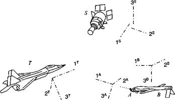
Fig. 3.11 UAV В tracking target T with antenna A and uplinking to satellite S. |
Rule 6: The transpose of the TM reverses the order of transformation ТВЛ = 17′ AB.
Rule 7: In transformation sequences, adjacent superscripts must be the same.
Example 3.2 Multiple Coordinate Transformations
Problem. The antenna A of an unmanned aerial vehicle В images the target T and sends the information to a satellite tracker S (see Fig. 3.11). The uplinked information consists of the following TMs: [T]rA, TBA. and [T]BS. How does the satellite processor calculate the TM of the target coordinates ]7 wrt its own coordinate system ]s?
Solution. String the TMs together according to Rules 6 and 7:
і’у’jSA j-y jSiS’
Notice that the sequence of adjacent superscripts is maintained if the transposed TM is replaced by Rule 6:
j-yjT’iS
These strings of TMs are quite common in full-up simulations. Naturally, you do not multiply them term-by-term, but leave the manipulations to the computer.
You may have noticed in Fig. 3.11 that the coordinate axes of the satellite do not meet. I offset them intentionally, to emphasize that coordinate systems have no origin and do not have to emanate from a common point. They are completely defined by direction and sense.
With deeper insight into the structure of TMs, we are prepared for the multitude of special coordinate systems and their associations. I will introduce the most important ones next, but defer some to later sections as they naturally occur in the context of specific applications.


