Drag and Lift Estimation on an Actual Airplane
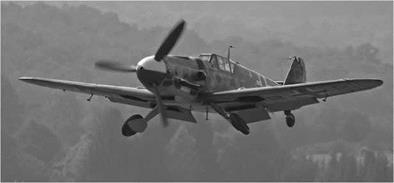
We consider what must be done to predict the aerodynamic performance of a flight vehicle that operates in the subsonic speed range (e. g., a World War II fighter). The Messerschmitt Bf-109G, shown in Fig. 9.2, was subjected to a long period of aerodynamic and powerplant refinement during its operational history. What we review briefly here is an elegant analysis by the famous aerodynamicist, Dr. Sighard Hoerner, who was involved in the refinement and testing of the Bf-109 in Germany in the 1940s (Hoerner, 1993).
To achieve a realistic assessment of the drag, it is clear that we must include the following:
• skin friction and profile drag on the fuselage
• skin friction and profile drag on the wing and tail surfaces
• induced drag
• drag due to surface imperfections such as bolt heads, rivet heads, sheet-metal blisters housing cannon components, aileron gaps, gaps around landing-gear wells, Pitot tube mounting, and sheet-metal lap joints and edges.
• drag of engine components such as air scoop, exhaust stacks, oil cooler, wing radiators, and ventilation openings
• interference drag due to tail wheel, antenna mast, canopy, and gun installation
|
Figure 9.2. Messerschmitt Bf-109G. |
|
Table 9.1. Messerschmitt Bf-109G aerodynamic configuration
|
The various contributions usually are separated into two groups: those directly due to the production of lift (i. e., the induced drag) and those not associated with the production of lift (i. e., the parasite drag). As we analyze the Bf-109G, we carefully distinguish between, these two types of drag. This is not always an easy task, because clearly, the tail surfaces and even the fuselage may contribute to the generation of lift.
Only the high-speed configuration with the landing gear and flaps retracted is considered here. To fully evaluate the performance and other qualities of the aircraft, other configurations covering the entire speed range must be analyzed similarly. For example, the configuration needed for landing or takeoff, with the flaps and landing gear deployed, involves an additional set of drag elements and related assumptions. We begin by examining the drag characteristics of the Bf-109G. Table 9.1 describes the aerodynamic configuration of this aircraft for high-speed flight at operational altitude.


