Our heavyweight helicopter equal in the world does not have
In Rostov started production of the most load-lifting rotary-wing car The Russian holding «Helicopt[...]

Everything about aircrafts and helicopters. News and events in aviation worldwide. Civil, transportation, military helicopters and airplanes.

Everything about aircrafts and helicopters. News and events in aviation worldwide. Civil, transportation, military helicopters and airplanes.

Everything about aircrafts and helicopters. News and events in aviation worldwide. Civil, transportation, military helicopters and airplanes.

Everything about aircrafts and helicopters. News and events in aviation worldwide. Civil, transportation, military helicopters and airplanes.


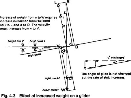
The addition of extra weight to a glider, assuming no other changes are made, will not affect the angle of glide or glide ratio, as Figure 4.3 shows. However, to support the additional load, the extra reaction force must be found, as indicated at R. This compels the model to fly faster down the glide path.* Ballasting a model glider does not affect the
|
|
glide ratio but does increase the sinking speed at any particular trim. Full-sized gliders frequently carry water ballast, sometimes totalling more than the pilot’s weight, to obtain good penetration, that is, good glide ratios at high speeds (Fig. 4.4). If thermals become weak, the ballast is jettisoned to reduce wing loading, W/S, and span loading, W/b, both of which reduce minimum sinking speed. There is no reason why model gliders should not adopt this technique. The advantage of jettisonable ballast for a R. C. glider is that the water may be dumped prior to landing, with much less danger to structure than the usual lead weight box. The ballast in full sized gliders is usually carried in plastic bags inside the * leading edges of the wings ahead of the main spar, so their effect on trim is slight The
•The increase in V will increase Re slightly and so change the character of the boundary layer. In practice any change in glide ratio resulting from this is small.
 |
:: Fig. 4.4 Effect of weight on penetration of sailplane
inertia in steep turns or in up-gusts actually relieves the spars of some up load. In landing the reverse occurs, so the water must go before touch down.
 |
|
Adding ballast does nothing to improve the basic aerodynamic design. If the design is bad, increasing W/S will improve penetration slightly at some cost in sinking speed for soaring. By the same token, reducing wing loading will help the sinking speed but at a high cost in speed performance. A well-designed sailplane with low drag will sink slower and penetrate better than a clumsy design. If it is light to start with there is still the option of adding or subtracting ballast as required by conditions (Fig. 4.5).
0
Plan and elevation drawings of Sigma w
Fig. 4.6 A sailplane with variable area and camber wings
44
|
Fig. 4.7
|
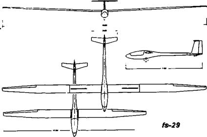
The FS-29, an experimental 13 to 19 metre sailplane with telescopic wings, enabling wing area and aspect ratio to be varied in flight: large span, high a. r., low span loading and low w/s for soaring, small span, low a. r. and high w/s for penetration. Compare with Figure 4.6 on p.44.