LATERAL-DIRECTIONAL MODELS AND MODES
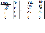
Going back to the nonlinear coupled differential equations defined in Equations 3.22, 3.23, and 3.28, the general free lateral-directional motion of an aircraft can be described by eliminating the V, a, q, and U equations from the 6DOF state model. This leaves us with the following set of differential equations:
g
b = — (cos b sin f cos U + sin b cos a sin U — sin a cos f cos U sin b)
+ p sin a — r cos a + Щ – Cywind + —- cos (a + sj) sin b mV mV
t> = j jX_j 2 {qSb(IzCi + IxzCn) — qr(llz + I2 — Iylz) + pqlxz {lx — Iy + fz)}
lXlZ Lxz
r = X 2 {qSb(IxCn + IxzCi) — qrIxz{lx — Iy + Iz) + pq{llz + Il — IxIy)}
jxjz xz
f = p + q tan U sin f + r tan U cos f
ф = r cos f sec U + q sin f sec U (5.23)
These equations and the a, q, and U equations in Equation 5.6 make it clear that having a pure lateral-directional motion, in the strict sense, is unrealistic. However, if the excursions are small, it may not be totally wrong to neglect the longitudinal motion altogether. Also, from Equation 3.30, we have
Cywind = Cycos b + Cd sin b
For small values of b, we obtain
![]() CYwind
CYwind
Since the variable ф does not appear in any of the equations for b, p, r, and f, the ф equation is generally omitted from the analysis. Using the above assumptions in b equation, a simplified set to describe the lateral-directional motion can be written as
One can find several approximate forms of the EOMs in the literature [1-4]. The above form of the lateral-directional EOMs, expressed using nondimensional force and moment coefficients, is of more general nature. Further, the coefficients CY, Cl, and Cn can be expressed in terms of stability and control derivatives using Taylor series expansion as discussed in Chapter 4.
 |
 |
||
Expressing the side force, rolling, and yawing moments in terms of dimensional derivatives, the following state-space model can be used to describe aircraft lateral – directional motion for most applications:
where u0 and 00 are the forward speed and pitch angle, respectively, under steady – state condition.
The above state model can be used to obtain the lateral-directional characteristic equation. Solving it for the eigenvalues will yield two real roots corresponding to the spiral mode and roll subsidence, while a pair of complex roots defines the Dutch roll (DR) mode. These three distinct lateral-directional modes are briefly discussed here.
Example 5.5
The Douglas DC-8 aircraft state-space lateral-directional model [4] is given as
|
T> |
-0.1 |
0 |
-468 |
32 |
v |
0 |
13.48 |
|||
|
P r |
= |
-0.0058 0.0028 |
-1.232 -0.0346 |
0.397 -0.257 |
0 0 |
P r |
+ |
-1.62 -0.0188 |
0.392 -0.864 |
|
|
Ф. |
0 |
1 |
0 |
0 |
ф. |
0 |
0 |
Obtain all the eight TFs using MATLAB. Obtain the characteristic modes of the aircraft dynamics.
Solution
The TFs are obtained by [numail, denail] = js2t/(a, b,c, d,1); [numrud, denrud] = ss2t/(a, b,c, d,2). For aileron input:
sysva = t/(numail(1,:),denail); syspa = t/(numail(2,:),denail); sysr = t/(numail(3,:), denail); and dampsystpha = t/(numail(4,:),denail).
For rudder input: sysvrud = t/(numrud(1,:),denrud); sysprud = t/(numrud(2,:),den – rud); sysrrud = t/(numrud(3,:),denrud); and systphrud = t/(numrud(4,:),denrud). These TFs are given in Table 5.2.
In fact this shows the feasibility of separately representing these modes in three different characteristic modes, since these modes seem to be reasonably well separated (Table 5.3).


