Local-level coordinate system
We conclude our exposition of coordinate systems with a special case of geographic coordinates, suitable for many aircraft and missile simulations. If the vehicle flies in the atmosphere with speeds less than Mach 5 (below hypersonic velocity), the Earth can be presumed an inertial reference frame. Furthermore, if the particular location on the globe is irrelevant to the simulation, any local tangent plane can serve as a geographic coordinate system, independent of the longitude and latitude designations. This special geographic coordinate system is called the local-level coordinate system. It maintains its fixed, level orientation, usually that of the launch point, although the vehicle is traversing the ground. Envision the longitude and latitude grid unfurled into this local-level plane. The vehicle’s trajectory is calculated relative to this plane, and altitude and ground distance are accurately portrayed. If you wanted to plot the trajectory on the globe, you could drape the ground track and altitude over the Earth’s curvature and assign longitude and latitude coordinates.
The local-level coordinate system ]L embeds its L and 2L axes into the horizontal plane and points the 3L axis downward. The direction of L is arbitrary, but, by convention, it is said to point north and the 2L axis to point east. For this reason it is sometimes also called the north-east-down (NED) coordinate system.
For those simulations that abide by these assumptions, you can replace the geographic by the local level coordinate system. The TMs derived in this chapter still maintain their validity. The body wrt geographic TM [TBG becomes [T]BL with the same Euler angles ф, в, and ф
cos ф cos в sin ф cos в —sin в
cos ф sin 0 sin ф — sin ф cos ф sin ф sin в sin ф + cos ф COS ф cos в sin ф COS ф sin в cos ф + sin ф sin ф sin ф sin в cos ф — cos ф sin ф cost? cos ф
(3.28)
 |
 |
|||
and the velocity wrt geographic TM |T]’/G is replaced by [TVL with the path angles x and у
Distinguish carefully that ]L is associated with frame E but is not ]G.
Have you kept up with the number of coordinate systems? Without the intermediate systems ]x, and Y I count a total of nine. That does not include the geodetic system, which will be introduced in Sec. 10.1.2, or the perifocal system,

 |
 |
 |
 |
||
Table 3.2 Summary of coordinate systems and their transformation angles
the subject of an exercise. As we discuss practical implementations, a few more will make their appearance in conjunction with seeker gimbals, variable nozzles, and INSs. For now, however, Table 3.2 summarizes the coordinate systems and transformation angles of this section.
3.2.2.8 Summary. Surely by now you are thoroughly familiar with frames and coordinate systems. I hope I have convinced you that they are different entities and not synonymous. Just remember that frames are physical, whereas coordinate systems are mathematical models.
We discussed the representation of a frame by base point and triad. The location of its base vector and the orientation of the triad determine the position of the frame. I defined the important heliocentric, inertial, Earth, and body frames. Then we moved over to the mathematical ward and dissected coordinate transformation matrices. We found them to consist of base vectors expressed in preferred coordinate systems or direction cosines of enclosed angles. I will spare you the drudgery of repeating the coordinate systems and their transformations, but point you again to Table 3.2 for a summary.
This wraps up the geometrical part of our exposition. With our tool chest filled we can model lines, planes, bodies, and reference frames, and place them into the Euclidean space with coordinate systems. However, so far time has eluded us. Now we must bring time into play and embark for the shores of kinematics, the study of motions in space and time.
Problems
3.1 Position of an aircraft relative to a tracking radar. The position of an aircraft A with c. m. A is to be defined wrt to a tracking radar R and its antenna, represented by point R. The radar is referenced to north. How do you model the aircraft’s and the radar’s location and orientation. Be specific in your definitions. Make a sketch.
3.2 Conversion of satellite velocity. The velocity of a satellite S wrt Earth E is measured in geographic coordinates [uf ]G. What are its coordinates in the heliocentric system ]я? Use the TMs that were introduced in Sec. 3.2.2.
3.3 Aerodynamic force component conversion. The aerodynamic force/is commonly coordinated in the stability system ]s by its components lift L, drag D, and side force Y, [/]s = [—D Y —L], In six-DoF simulations, however,/is frequently expressed in body coordinates [f]B = X Y Z], Derive the conversion transformation between the two component forms.
3.4 Transformation matrix between satellite and inertial coordinates. The
normal satellite coordinate system ]s (see Ref. 1, p. 46) is used to express drag forces on a satellite B. The Is axis is parallel to the satellites inertial velocity v’fi, the 2s axis normal to the orbital plane, and the 3s axis in the general direction of the satellite’s displacement vector from the center of the Earth sB/. Given [u^]7 and [ід/]7 in inertial coordinates, express the TM |T]S7 in terms of these two vectors.
|
|
3.5 Angle of missile from north. The TM of the body wrt geographic coordinates TBG is given by Eq. (3.14). How do you determine the angle between the centerline of the missile and the north direction?
3.6 Euler angles of gyro dynamics. The elements of the direction cosine matrix, Eq. (3.14), contain the trigonometric functions of the Euler angles. More precisely they should be called the Euler angles of flight mechanics. In the study of the dynamics of gyroscopes, a different set of Euler angles is frequently used. Although the same symbols ф, в, and ф are adopted, the TM of body coordinates wrt inertial coordinates uses the sequence 3 > 1 > 3 and not 3 > 2 > 1 as in the case of flight mechanics. Make an orange peel diagram and derive the TM of gyro dynamics [T]BI with the sequence ]B <^—Y <~—x Compare the two
transformations. Are there any similarities?
3.7 Sequence of transformation is all important. The standard Euler transformation of flight mechanics [TBG is sequenced n <^—]G and
also called the 3 > 2 > 1 transformation. Let us reverse the sequence to 1 > 2 > 3 or]G +—~]x -^—]Y <^~]B and name it [T]GB. Sketch the orange peel diagram and derive T]GB. Is [T]GB the transpose of [T]BG? Why not? What is the sequence of transformation for the transpose of [T]BG?
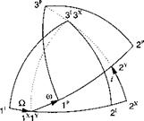
3.8 Perifocal coordinate system. The trajectory of a satellite is best described in the perifocal coordinate system. Determine the transformation matrix TPI of the perifocal wrt inertial coordinates given in the figure. The sequence of individual transformations is 3 > 1 > 3, or in symbolic form ]p ]x <—];, with
Q the longitude of the ascending node, і the inclination, and ш the argument of the periapsis. These three angles are part of the six orbital elements that describe size, shape, and orientation of a satellite orbit. The remaining three are the semimajor axis and eccentricity of the elliptical orbit and the time of the periapsis (closest point to the Earth) passage.
|
|
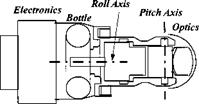
3.9 Seeker wrt vehicle transformation matrix. An infrared seeker head of a missile has two gimbals. Its inner gimbal with the optics and the focal plane array executes pitching motions while its outer gimbal allows for rolling excursions. Two coordinate systems are of interest: the body coordinates ]B with the 1H axis parallel to the roll axis, pointing forward, and the head coordinates ]H with the 2H axis parallel to the pitch axis, pointing to the right. Determine the transformation matrix [T]HB of the head coordinates wrt the body coordinates using the roll angle фнв and pitch angle Ohb – Sketch the orange peel diagram, clearly indicating the two angles.
|
|
3.10 Antenna angles and transformation. The main beam of a radar antenna is deflected by the azimuth az and elevation <?/ angles from the centerline of the missile 1B. The transformation sequence is 3 > 2 or symbolically ]A ]x Iй.
Make an orange peel diagram and derive the TM T]AB. What are the coordinates of the antenna base vector [a]B in body coordinates? What are the angles between Iа, 1B; 2a, 2b; and 3A, 3B? (Hint: Use direction cosine matrix form.)
|
1A
/ / |
3B ‘
3.11 Initialization of flight-path angles. To initialize six-DoF simulations, it is most convenient to use the Euler angles і(г, в, ф and the incidence angles a, fi.
(a) Given these angles, derive the equations that determine the flight-path angles X and y.
(b) Introduce coordinate systems and express the equations in a form suitable for programming.


