14.10.4 Airframe Flows
As explained in Chapter 11, the flow over a helicopter fuselage is extremely complicated because it is often dominated by complex viscous effects occurring within the boundary layer. There is often the possibility of grossly separated flow and recirculation especially near regions of high surface curvature. Furthermore, the flow is often highly unsteady as a result of periodic forcing from the nearby passage of the rotor blades and localized interactions with the rotor wake, especially on the tail-boom and empennage under certain flight conditions (see Section 11.2.2 for a detailed discussion). Predictive capabilities for pressure and skin friction drag are not yet mature. Current capabilities for design are based on synthesis of component drag using experimental data or by using a combination of experimental data and potential flow theory.
Although panel methods (see Section 14.7) are very flexible and can aid considerably in the design process, they are unable to confidently model viscous effects and separated flows typical of helicopter fuselage shapes and especially hub designs. However, empirical and semi-empirical corrections for the viscous effects can be incorporated into the basic method. For example, a 3-D boundary-layer method can be coupled by means of displacement corrections or by means of a transpiration velocity to the fuselage shape – see Lindhout et al. (1981) and de Bruin (1987). The advantage to the latter approach is that only the right-hand side of Eq. 14.40 is affected, thereby avoiding an expensive recalculation of the influence coefficients at every computational time step. The separated wake can be modeled as a vortical shear layer, the shape of which is either prescribed or made to be force free, as mentioned previously, but this also changes the influence coefficients. Furthermore, a prerequisite is that the separation line be calculated (say from a 3-D boundary layer solution) or deduced from experiment (say from surface flow visualization).
Overall, panel methods and semi-empirical modifications and corrections thereof have been shown to give good predictions of the surface pressure on isolated helicopter fuselages – see Polz & Quentin (1981), Polz (1982), Ahmed et al. (1988). Ahmed (1990) gives a good overview of the various predictive models in current use and their capabilities in predicting pressure distributions and drag on helicopter fuselages. Chaffin & Berry (1994) show that panel methods give good agreement with experimental measurements of fuselage surface pressure, and the predictions are just as good as Navier-Stokes approaches except in regions with large-scale flow separation. See also Narramore & Brand (1992).
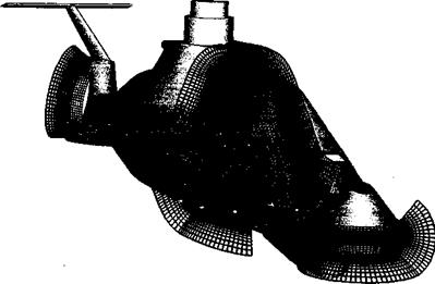
CFD methods for airframe design are still in the development stage and are relatively far from being practical for use in routine helicopter fuselage design studies. The use of Navier-Stokes based CFD methods has the potential to help understand a number of problems associated with airframe aerodynamics and rotor-airframe interactional aerodynamics but, like several other problems in helicopter aerodynamics, the proper modeling of flow turbulence and flow separation remains a significant challenge. Another problem with CFD when applied to airframe calculations is the efficient generation of grids. Some progress is being made with hybrid grid systems that couple the advantages of structured and unstructured grids. An example of a CFD grid around a modem military helicopter is shown in Fig. 14.13, showing that this approach is really quite complex compared to a surface panel method such as that shown in Fig. 14.4. Rapid progress in grid generation techniques and solution algorithms is being made – see, for example, Berry et al. (1994), Chaffin & Berry (1994), Duque & Dimanlig (1994), Duque (1994), and Renaud et al. (2004), and it is likely that significant inroads toward an improved understanding of airframe aerodynamics and rotor-airframe interactions using these new methods will occur in the coming years. New numerical algorithms are being developed that will quickly and automatically generate computational grids for CFD analyses. This may allow CFD techniques to be used early on in the design and refinement of airframe shapes – see, for example, Naducci et al. (2003).
Meakin & Wissink (1999) have used overset structured grids to discretize the relatively complicated RAH-66 Comanche fuselage geometry, as shown in Fig. 14.13. See Meakin (1995, 1997) for details. Grid components are arranged to conform to the shape of the airframe, which, perhaps somewhat fortuitously in this case, was designed with relatively flat surfaces to reduce radar returns as a primary goal. Multiple grids facilitate resolution of the viscous boundary layer and important off-body aerodynamics. The near-body portion of the grid was decomposed into 110 components containing a total of approximately
2.2 million grid points. The off-body grid system included 233 components and 5.1 million points for a total of 7.3 million points in all. The flow solution has been used to examine
|
Figure 14.13 The generation of CFD grids around modem military helicopter airframes requires substantial effort in time and cost. Source: Image courtesy of NASA Ames and Robert Meakin, US Army AFDD. |
|
Figure 14.14 Unsteady flow over an isolated Comanche helicopter fuselage using a Navier-Stokes method. Particles released from the base of the main rotor hub. Instantaneous Mach number field on a plane at longitudinal centerline. (Side View). Source: Image courtesy of NASA Ames and Robert Meakin, US Army AFDD. |
the effects of the turbulence in the main rotor hub wake on the unsteady aerodynamics at the tail – see Fig. 14.14. This is a good example of where CFD can provide much insight into a real problem that would be extremely time consuming and expensive to examine using either wind tunnel experiments or flight tests – see Berry (1997). Notice though that in this example, no representation of the rotor was included at all within the computation. Indeed, a major future goal is to be able to model, in fully coupled fashion, the interaction between the rotor and fuselage flows. Achieving this goal with the Navier-Stokes equations is still some distance in the future but will allow the unsteady effects of the rotor wake on the dynamics of the airframe to be examined, for instance, to determine the causes of the transient pitching moments that occur on some helicopters as the empennage moves in and out of the rotor wake during changes in flight speed (see Section 11.3.1).
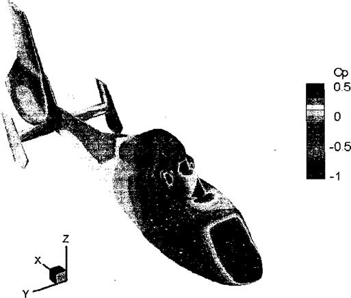
Accurate modeling of the unsteady, localized interactions that take place between the fuselage and vortices from the rotor wake would enable designers to adopt less expensive approaches to minimizing fuselage weight, vibrations, cabin noise, and component fatigue. The results of advanced calculations such as these, when generated early enough in the design process to be of use, might prevent some of the expensive design mistakes that have been made in the past. This is a significant motivation for CFD practitioners. The current state of the art in coupled rotor-fuselage modeling falls somewhat short of this lofty aim, however. One interesting approach results from weakening the coupling between the aerodynamics of the rotor and fuselage – see, for instance, Zori & Rajagopalan (1995), Brezillon (2000), Renaud et al. (2003,2004), and D’Alascio et al. (2003). In this approach, a full Navier-Stokes model for the fuselage is augmented by embedding a series of disks representing the rotors into the computational grid. A pressure jump across the disks is then imposed to represent the lift generation by the rotors, and some representation of the rotor wakes then develops in the computation as a result of the discontinuity in pressure around the edges of the disks. The pressure jump across the rotor disk quite often is calculated by using a comprehensive rotor model (see Section 14.11) to determine the time-averaged loading distribution over the rotor disk for the flight condition being modeled. In this way the time-averaged effects of the rotor on the fuselage can be represented. These methods are ideal for parametric studies at the design stage and can help give key insight to potentially unforeseen problems, even though computation time and cost is still relatively high. Panel methods, however, remain much more cost effective for design purposes than any of the other types of CFD approaches.
|
Figure 14.15 Predictions of the time-averaged pressure over the airframe of a helicopter in forward flight using a momentum-source representation of the rotor and a Navier-Stokes based flow solver for the airframe flow. Source: Image from Renaud et al. (2004). |
More recent work by Park et al. (2003) and Renaud et al. (2004) has shown the continuing success of Navier-Stokes based methods in predicting airframe loads (see also Chapter 11). An example of such a Navier-Stokes calculation is shown in Fig. 14.15, where good agreement with measured airloads was also obtained. It is likely, however, that in the future various types of methods will be used in a more complementary fashion in design work, providing an improved predictive capability of airframe aerodynamics and elimination of possible adverse rotor-airframe interaction problems before helicopters make their first flights. Bear in mind though that the reciprocal coupling, giving the effects of the fuselage on the rotor, are not well represented using this approach and that the similarities between the fully unsteady situation and the aerodynamic behavior of the fuselage when forced by a steady rotor flow can sometimes be rather tenuous.


