Axis and Angle of Rotation
You have learned that a rotation tensor is orthogonal with the determinant value + 1. Conversely, every orthogonal 3×3 tensor with determinant +1 represents a rigid right-handed rotation. Given such a rotation tensor, how do we calculate its rotation axis and rotation angle?
4.1.3.1 Determination of the axis of rotation. Let и be the axis of the rotation tensor/?. Because rotating the rotation vector about itself does not change its direction or length, n = Rn. The invariancy of n holds also if the sense of the rotation is reversed: n = Rn. Subtracting both equations yields (R — R)n = 0. For any allowable coordinate system, say ]A,
([R]A – [£]A)[n]A = [0]A
Now, substituting the elements of the rotation tensor
![]() (4.15)
(4.15)
we obtain
|
0 |
-i. r21 – Г12) |
(r13 – r3l) |
n |
0 |
|
|
(r21 – rX2) |
0 |
(r32 – r23) |
n2 |
0 |
|
|
(r 13 – Cn) |
(T?2 – r22) |
0 |
из |
0 |
The left-hand side is a vector product. Therefore, for the nontrivial case, the vector equivalent of ([/?]A — | ^J4) is parallel to [nA with the scaling factor k
 (4.16)
Choose к such that и is a unit vector, pointing in the direction given by the right – hand rule. As a scaling factor, к is the same for all allowable coordinate systems. To calculate it, we chose the most convenient coordinate system, that is, B, such that
 (4.17)
Substituting into Eq. (4.16),
 1
1
1 sin іjr
If jr were known, к could be calculated, and Eq. (4.16) would provide the u vector of rotation. Let us determine ifr.
4.13.2 Determination of the angle of rotation. Determining the ang of rotation is simplified by the fact that the trace of a tensor is preserved und transformation. We can take the trace of Eq. (4.17) and set it equal to the diagon elements of the general rotation tensor Eq. (4.15):
1 + 2cos f = Щ + гг 2 + r33
Solving for іjf gives the desired equation
In summary, for a rotation tensor [ft]4, coordinated in any allowable coordinate ]4, the angle and axis of rotation are given by the following equations:
If [ft]4 = [ft], then ф is zero, and [nf is undefined.
Example 4.4 Satellite Positioning
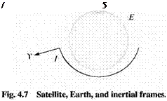
Problem. A satellite S is placed into a geosynchronous orbit. The onboard INS provides its initial orientation So wrt the inertial frame I by the rotation tensor Rs,)l (see Figure 4.7). To point the satellite’s antenna at the Earth ft, it needs to be adjusted such that its new orientation with respect to the Earth conforms to the rotation tensor RS, E. The most fuel-efficient way to torque the satellite is by direct rotation about an inertial axis. Provide the equations for the INS based attitude controller.
Solution. The rotation tensor to be achieved by the attitude controller is Rs l — RSl /;ftc/, where RE! is known from almanac tables. Therefore, the satellite has to be rotated by
RSlS,> = ftS|/ftSo/ = Rs’ERE! RSo1 (4.19)
Because the INS provides the main reference of the satellites, the unit vector of rotation should be declared in inertial coordinates. In preparation we express Eq. (4.19) in inertial coordinates
[RSAo]1 =
Yet. most likely, the RS’E tensor is given in Earth coordinates [ /?’’’ E]l:. Therefore, Eq. (4.19) becomes, in coordinated form,
![]()
 |
L Rs, s°]’ = [TYZiR^fm^lRZ’YiR^]1
With [f? SlSo]7 thus given, and its coordinates labeled as
|
f 11 |
П 2 |
r 3 |
|
Г2Х |
Г22 |
Г23 |
|
-Гз |
Г32 |
ГЗЗ- |
we apply Eq. (4.18)
and thus Eqs. (4.20) and (4.21) are the equations for the attitude controller.


