
Our heavyweight helicopter equal in the world does not have
In Rostov started production of the most load-lifting rotary-wing car The Russian holding «Helicopt[...]

Everything about aircrafts and helicopters. News and events in aviation worldwide. Civil, transportation, military helicopters and airplanes.

Everything about aircrafts and helicopters. News and events in aviation worldwide. Civil, transportation, military helicopters and airplanes.

Everything about aircrafts and helicopters. News and events in aviation worldwide. Civil, transportation, military helicopters and airplanes.

Everything about aircrafts and helicopters. News and events in aviation worldwide. Civil, transportation, military helicopters and airplanes.


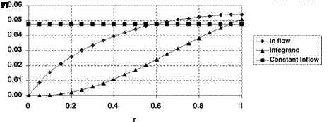
Applying Equation 3.32 for the three-quarters radius point, at which У is 7.5°, gives a thrust coefficient CT = 0.0091. Turning now to Equation 3.36, the non-uniform l varies along the span as shown in Figure 3.5.
Superficially this is greatly different from a constant value – Equation 2.12. Nevertheless, on evaluating Equation 3.36 the variation of (Or2 — 1r) is as shown in the figure, from which the integrated value of thrust coefficient is CT = 0.0092. Thus the assumption of constant inflow has led to underestimating the thrust by a mere 1.7%. The result agrees well with Bramwell’s general conclusion (p. 93) and confirms that uniform inflow may be assumed for many, perhaps most, practical purposes.
3.2 Ideal Twist
The relation in Equation 3.36 contains one particular situation when l becomes a constant, that is if the term Ox is itself constant, then:
![]()
 |
Ox — Otip
OTIP being the pitch angle at the tip. This nonlinear twist is not physically realizable near the root but the case is of interest because, as momentum theory shows, uniform induced velocity corresponds to minimum induced power. The analogy with elliptic loading for a fixed-wing aircraft is again recalled. The twist defined in Equation 3.37 is known as ideal twist. Inserting in
= Sa (-tip—l)
and, since l = xf = f TIP, the tip inflow angle, Equation 3.38 can be expressed as:
With ideal twist and the resulting constant value of l we find Equation 3.36 simplifies to:
and the direct relationship between – and CT is now:
![]() -tip = 2 + Ct
-tip = 2 + Ct
sa 2
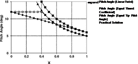 |
Some pitch angles for ideal twist and linear twist are compared in Figure 3.6.
 |
|
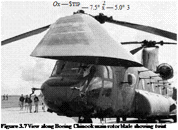
The inboard end of the blade is assumed to be at r — 0, ignoring for the purposes of comparison the practical necessity of a root cutout. The linear twist is assumed to vary from 12° pitch at the root to 6° at the tip. Figure 3.7 shows a typical main rotor blade. The built-in twist is readily observed. A straightforward comparison is when the ideal twist has the same pitch at the tip—we see that unrealistically high pitch angles are involved at 40% radius and inboard. A more useful comparison is at equal thrust for the two blades. From Equations 3.32 and 3.41 it follows that for the same thrust coefficient the pitch angle at two-thirds span with the ideal twist is the same as that at three-quarters span with the linear twist, which for the case in point is 7.5°. Thus the ideal twist is given by:
 |
This case is also shown in Figure 3.6. The two twist distributions give the same pitch angle when:


