Tip Vortex Formation
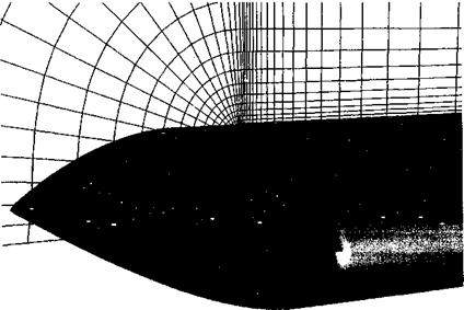
Trailing vortex formation is a complex fluid dynamics problem and is still not yet fully understood. It involves the interaction between strong pressure gradients and viscous shearing forces in the highly 3-D flow near the tips of the rotor blades. Resolving the flow in this region requires a large number of grid points carefully contoured to the blade shape – see Fig. 14.9. While fundamentally the process of vortex formation can only be solved using the Navier-Stokes equations, some success in predicting the behavior of the vortex after formation has been achieved using the Euler equations. Clearly, the proper modeling of the formation of the tip vortex and the subsequent convection of the vorticity through the flow field is probably the most important single step in the calculation of the entire rotor flow field. The difficulties encountered by most Navier-Stokes based CFD methods in preserving the wake vorticity to sufficiently far behind the blades for its effects on the rotor to be captured properly has led to the development of various adaptive gridding or vorticity capturing schemes – see Kim et al. (2002) for a review. Because of the extremely intricate physical processes governing the formation of the tip vortex, most CFD methods (when applied to solve this problem) exhibit solutions that are grid dependent – solution of the governing equations on grids that are sufficiently fine to produce converged solutions is still prohibitive in terms of computational cost for any form of routine use. The goal is to reach some compromise between fidelity and cost, but this requires further research and, especially, validation with experimental measurements. The scope and extent of tip vortex measurements have been discussed in Chapter 10.
|
Figure 14.9 Example of the fine computational grid needed at the tip of a helicopter rotor blade to resolve the roll-up of the concentrated tip vortex using a Navier-Stokes approach. Source: Grid courtesy of Karthikeyan Duraisamy. |
To help in reaching this computational goal, various techniques for wake capturing using grid adaptation show promise. These techniques allow grid points to be clustered where the spatial and temporal gradients in the flow are highest and so require a lower overall number of grid points compared to methods using regular grids. Chimera grid systems do much to help resolve the difficulties associated with modeling the flow over blades that are rotating within a domain in which the flow is either stationary or can be represented as a constant free-stream far away from the rotor – see Duque (1992), Strawn et al. (1998), Ahmad & Strawn (1999), Pomin & Wagner (2002), and Strawn & Djomehri (2002). For instance, a surface-conforming grid that rotates with the rotor can be used to capture the flow near the rotating blades while a background Cartesian grid can be used for the wake, with information being exchanged between the grids using various interpolation techniques.
Another method of controlling the dissipation of wake vorticity is by using a vorticity confinement or vorticity embedding technique – see Steinhoff (1987) and Steinhoff & Ramachandran (1990), whereby an “anti-diffusion” term is added to the Euler equations to help control the otherwise nonphysical spreading and diffusion of the tip vortex as it evolves downstream of the blade tip. There are, however, problems with this technique in regard to nonphysical effects and the anti-diffusion must be turned off, for example, for В VI problems. New developments in vorticity embedding techniques for rotor wake predictions are described by Bhagwat et al. (2005), where wake vorticity, as computed using circulationcarrying wake markers, is embedded into the full-potential equation. This novel approach attempts to fuse the best elements of Lagrangian free-vortex schemes with Eulerian grid – based CFD schemes to give a numerically efficient solution for rotor wake problems.
All of these methods are relatively expensive from a computational standpoint and so have not yet made a significant impact on practical rotor design problems. Furthermore, these methods need much further validation, particularly for rotors with advanced tip shapes and also for forward flight applications where shock waves might be present on the advancing blade. Only then can they be used with any confidence to design helicopters. Meanwhile, significant effort still needs to be spent in validating these models against experimental measurements made on properly idealized problems before the entire helicopter can be tackled as a whole. To this end several sets of detailed flow field measurements on generic rotors have provided reliable data for the validation of various types of computational models – see McAlister (1995, 1996), Mahalingam & Komerath (1998), and Martin et al. (2003).
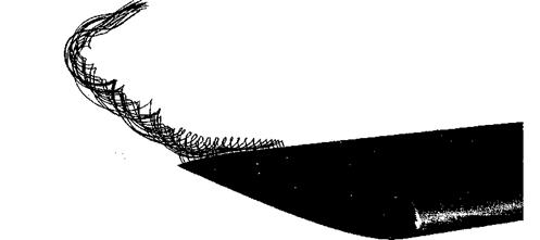
An example of a Navier-Stokes prediction of the rollup of a tip vortex from a helicopter blade is shown in Figs. 14.10 and 14.11, which are from Duraisamy & Baeder (2004). Basically the calculations show that the flow on the lower surface follows a favorable pressure gradient toward the upper surface. Immediately behind the trailing edge of the blade there is evidence of two concentrated regions of vorticity, but these rapidly merge to form a single concentrated tip vortex. This behavior is consistent with experiments – see, for example, Martin, Leishman, & Pugliese (2003). The sharp edges on the blade tip always tend to promote flow separation, and this makes the consideration of viscous effects very important in terms of predicting the subsequent roll up and evolution of the tip vortex. Combined with this is the entrainment of the turbulent vortex sheet trailed from the inner part of the blade. This sheet is formed by the confluence of the boundary layers on the upper and lower surface of the blade – see also Fig. 10.7. The interaction of the sheet with the roll up of the flow from the tip appears to cause large decelerating forces and the generation of turbulence inside the core, emphasizing again the underlying complexity of tip vortex formation and the need for a full Navier-Stokes approach if the roll up is to be predicted properly.
|
Figure 14.10 Particle tracers showing the roll-up of the tip vortex from a helicopter blade predicted using a Navier-Stokes solver. Source: Calculation and image courtesy of Karthikeyan Duraisamy. |
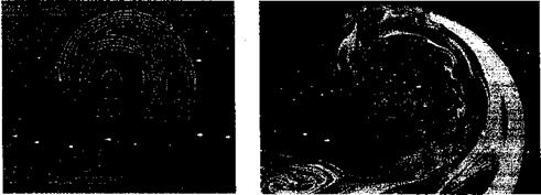
A calculation of the structure of the vortex flow at a later time (145° of wake age in this case) is compared with flow visualization in Fig. 14.11, where there is good qualitative agreement at least. The actual structure of the rolled up tip vortex is comprised of three zones: 1. An inner laminar region with no mixing between layers, 2. A transition region where there are eddies of various scales, and 3. An outer turbulent region. The high swirl
ігрілрЇНрс nPdr tbp xrrvrtPY РПГР rponlf in bt rrb x/qIiipc rtf fbp Inpol Dipbor/Іслп mimkar
TVIVVIUVJ 11VU1 U1V V V/Д. IV/Д WXV ±11 lllgil T U1UVO VI U1V JLWUX 1VJLV11U1UOV11 JLlUiUL/Vl UlVtV
(see Section 10.6.5) and, because of stratification effects, turbulence cannot be generated or sustained. This is essentially a vortex Reynolds number effect and will result in essentially zero eddy viscosity in the core, although this is not properly represented by the turbulence model used within the CFD analysis. These observations suggests that the development of turbulence models used in CFD methods for vortex flows still has some way to go before
|
(a) Navier-Stokes simulation (b) Experimental observation
Figure 14.11 The roll-up and final formation of the tip vortex is a complicated process involving viscous shear and turbulence. Left: CFD calculation showing phase-averaged eddy viscosity contours. Right: Phase-resolved flow visualization. Both results for 145° of wake age. Source: Navier-Stokes calculation and image courtesy of Karthikeyan Duraisamy; Flow visualization courtesy of Manikandan Ramasamy. |
predictions of blade generated tip vortices can be made with sufficient fidelity to account for Reynolds number scaling effects.


