Six-Degrees-of-Freedom Simulations
The ultimate virtual environment for aerospace vehicles is the six-DoF simulation. No compromises have to be made or shortcuts taken. The equations of motion model fully the three translational and three attitude degrees of freedom.
Any development program that enters flight testing requires this kind of detail for reliable test performance prediction and failure analysis. Fortunately, by that time the design is well enough defined so that detailed aerodynamics and autopilot data are available for modeling. Yet, the development and maintenance of such a six – DoF simulation consumes great resources. Industry dedicates their most talented engineers to this task and maintains elaborate computer facilities.
However, even in the conceptual phase of a program it can become necessary to develop a six-DoF simulation. This need is driven either by the importance and visibility of the program or by the highly dynamic environment that the vehicle may encounter. A good example is a short-range air-to-air missile intercepting a target at close range. Its velocity and attitude change rapidly, resulting in large incidence angles and control surface deflections.
Six-DoF simulations come in many forms. They can be categorized by the inertial frame (elliptical rotating Earth or stationary flat Earth), by the type of vehicle (missile, aircraft, spinning rocket, or spacecraft), or by the architecture (tightly integrated, modular, or object oriented). We derive here the general translational equations for elliptical and flat Earth and leave the detail to Chapter 10.
5.4.3.1 Round Earth. The translational equations for round Earth—be it spherical or elliptical—follow the same derivation used in three-DoF models. As we will discuss in the next chapter, even for six DoF, the trajectory can be calculated as if the vehicle were a particle. Therefore, we can be brief. Newton’s law related to the J2000 inertial frame as applied to a vehicle with aerodynamic, propulsive, and gravitational forces is
mD’vlB = f а p + mg
The integration is executed in inertial coordinates, but the aero/propulsion data are most likely given in body coordinates. We make those adjustments together with the expression of the gravitational acceleration in geographic coordinates:
![]() ™[£>Ч]7 – [t]BI[frp]B +m[T}GI[gf
™[£>Ч]7 – [t]BI[frp]B +m[T}GI[gf
The main distinction with the three-DoF formulation, Eq. (5.31), lies in the handling of the aero/propulsive forces. Six-DoF simulations model the complex aerodynamic tables and propulsion decks in body coordinates, whereas their simple approximations in three-DoF simulations can be expressed in velocity coordinates.
Another set of differential equations provide the position traces
![]() (5.40)
(5.40)
which will have to be converted to more meaningful longitude, latitude, and altitude coordinates.
5.4.3.2 Flat Earth. Even in six-DoF simulations, with all of their emphasis on detail, the flat-Earth models are prevalent. All aircraft simulations that I know of are of that flavor, as well as cruise missiles and tactical air intercept and ground attack missiles. Earth E becomes the inertial frame, and the longitude/latitude grid
is unwrapped into a plane. Newton’s law takes on the form
mDEvEB = fap+mg
The majority of flat-Earth six-DoF models express the terms in body coordinates, save the gravitational acceleration. By this approach the geographic velocity [vB]B in body coordinates can be used directly to calculate the incidence angles [see Eqs. (3.20-3.23)]. The conversion should be familiar to you by now. Transform the rotational derivative to the body frame
and coordinate accordingly
![]() [fiB£]B[u£]B + – Ua, p]B + [T]BL[g]L (5.41) L J m
[fiB£]B[u£]B + – Ua, p]B + [T]BL[g]L (5.41) L J m
This is the translational equation of motion for flat Earth, implemented in six-DoF simulations. One more integration completes the set:
![]() (5.42)
(5.42)
The body rates [SlBE]B are provided by the rotational equations (see next chapter), and the direction cosine matrix [T]BL is calculated by one of the three options provided in Sec. 4.3.
On the CADAC CD the GHAME6 simulation provides an example of the elliptical Earth implementation, and the flat-Earth model is used in SRAAM6. By running the sample trajectories, you can learn much about the world of six-DoF simulations.
Much more will be said in Chapters 8-10 about each of the three levels of simulation fidelity. At this point you can proceed directly to Chapters 8 and 9 to deepen your understanding of three – and five-DoF simulations. All of the necessary tools are in your possession. To tackle the six-DoF simulations, you first need to conquer the next chapter and its Euler law of rotational dynamics. Thereafter you are ready for the ultimate six-DoF experience of Chapter 10.
Let us pause and look at our newly acquired tools. The linear momentum, called motion variable by Newton, is related to mass and velocity bypB = mBv’B. It takes on the vector characteristics of the linear velocity, multiplied by the scalar mass of the vehicle. Our modeling elements, points and frames, are sufficient to define it completely. We could have carried over the superscript В of mass mB to define pBJ, but I decided to drop it because of the particle nature of body В in Newton’s law.
The other new vectors we encountered are the external forces. They consist of fa, the aero/propulsion surface forces, and mBg, the gravitational volume force. Both types must be applied at the c. m. of the vehicle. Only then can the vehicle be treated as a particle. In the next chapter, when we add the attitude motions to the translations of a body, we will derive the effect of shifting the forces to other reference points.
References
’Newton, I., Mathematical Principles of Natural Philosophy (reprint ed.), Univ. of California Press, Berkeley, CA, 1962.
2Franke, H., Lexikon der Physik, Frank’sche Verlagshandlung, Stuttgart, Germany, 1959. 3Grubin, C., “On Generalization of the Angular Momentum Equation,” Journal of Engineering Education, Vol. 51, No. 3, Dec. 1960, pp. 237, 238, 255.
Problems
5.1 Linear momentum independent of reference point. Show that the linear momentum pB of a body В wrt the inertial frame l and referenced to the c. m. В depends only on frame I and not on a particular point I.
5.2 Transformation of body points. The linear momentum pBi of a rigid body В relative to the inertial frame I and referred to an arbitrary body point B is shifted to another body point Вг – Prove the transformation equation
Pb2 — Pb, +mBnB, sBlB2
starting with the definition of the linear momentum of a collection of particles Eq. (5.2).
5.3 Satellite release. The space shuttle В releases a satellite S with its manipulator arm at a velocity of
[u| ]B =[0 0 —at]
with the constant acceleration a. Its circular orbit is in the 17, 37 plane of the J2000 inertial coordinate system ]7 at an altitude of R and period of T, maintaining its 3B axis pointed at Earth’s center. Initially, the l7 and B axes are aligned, and the space shuttle flies toward the vernal equinox. Individual masses are mB and ms, respectively. Derive the equation for the inertial acceleration of the space shuttle first as a tensor DrvB, then coordinated [du^/dt]r, and finally in components.
|
|
5.4 What’s the difference? The selection of the inertial frame for Newton’s law is determined by the application. The statement was made that for near-Earth orbits the J2000 inertial frame I can be used. What error is incurred by using mBDlv, B — /instead of the heliocentric reference frame H, mB DHvB = fl
(a) Derive the error term in tensor form.
(b) Coordinate it in heliocentric coordinates.
(c) Give a maximum numerical value for the error. You can assume a circular orbit of Earth around the sun.
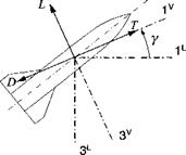
5.5 Planar trajectory equations of a missile. Derive the planar point-mass equations of a missile in velocity coordinates ]v with the dependent variables V as velocity magnitude and у as flight-path angle. Lift L and drag D are given, as well as the thrust T in the opposite direction of D.
(a) Derive the translational equations in an invariant form consisting of the velocity and position differential equations.
(b) Coordinate the equations into matrix form.
(c) Multiply out the matrix equations, and write down the four component equations.
|
|
5.6 Centrifugal and Coriolis forces, who cares? An aircraft flies north with the velocity V at an altitude h above sea level. With the flat-Earth assumption we use Newton’s law in the simple form mBDEvf = /, but neglect on the right- hand side the Coriolis and centrifugal forces mB(2f2£/v| + ftE1flEISBE)- What are the values of these accelerations and their directions at 60-deg latitude (use h = 10,000 m, V = 250 m/s) in geographic coordinates?
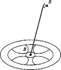
5.7 Hiking in the space colony. Wernher von Braun dreamed of a large space colony S orbiting Earth in the shape of a wheel with spokes. For artificial gravity the wheel was to be revolving with a>s about its 3s axis, and its close link with Earth was maintained by keeping the spin axis pointing toward Earth. You are hiking from the hub through a spoke toward the rim along the 2s axis. What are the Coriolis and centrifugal forces in ],s coordinates that you have to counteract to prevent you from bumping into the walls?
5.8 Space station rescue. A large, rigid, and force-free space station has a malfunctioning INS and begins to tumble in space. The chief engineer needs an alternate method to determine the angular velocity ujbi of the station В wrt the inertial frame I in order to supply it to the stabilizing momentum wheels.
A radio navigation system R is located on a long boom and displaced from the space station c. m. В by sRls. It measures its inertial velocity [vlRK and time rate
of change [d))^/dr|fl in space station coordinates ]B. Provide the chief engineer the matrix form of the differential equation [a>BI]B so that he can program it for the onboard computer. The mass of the boom and the navigation system may be neglected. (The orbital velocity [vjj]7 remains unaffected and is known from the orbital elements of the space station.)
|
|
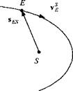
5.9 Kepler’s law from Newton’s law. Derive Kepler’s second law from Newton’s second law by considering a particle (Earth E) acted upon by a central force — lises/ses^, where S is the center of the sun and ji the gravitational parameter in meters cubed per seconds squared (± = Gmsun, G is the universal gravitational constant).
|
|
Hint: Kepler’s second law states that the line joining Earth to the sun sweeps out equal areas in equal time. In other words, the area swept out in unit time is constant. With v| the velocity of Earth wrt the sun, this statement translates into the vector product Sesvse = const. You should prove that Newton’s second law reduces to this relationship.
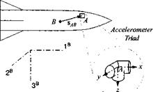
5.10 Accelerometer compensation, (a) An accelerometer triad A with its sensors mounted parallel to the missile body axes ]B is displaced sABB from the missile c. m. B. What are the three specific force components [aB]B acting on the missile, given the three accelerometer measurements aA]ri, the vehicle angular velocities
о)ВІУ‘ = p q r]
and their accelerations
d/dt[<wB/]B = [p q r]
(b) The acceleration triad is displaced by = [1 0 0] m, and the missile
executes steady coning type motions represented by
[a>BI]B = [0 sin t cos t] rad/s
What are the correction terms [Даa]b for the three accelerometer measurements?
|
|
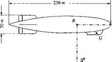
5.11 Burp of Graf Zeppelin. In October 1924 the Graf Zeppelin crossed the Atlantic on its maiden voyage under the command of Dr. Hugo Eckener. Midway it encountered a gust that caused the ship to pitch up at a constant 10 deg/s and incremental load factor of 0.1 g. What was the linear acceleration that Dr. Eckener experienced in the gondola at point G in Zeppelin coordinates? The displacement from the ship’s c. m. is [5Ig]b = [—90 0 —15] m.
|
|


