Our heavyweight helicopter equal in the world does not have
In Rostov started production of the most load-lifting rotary-wing car The Russian holding «Helicopt[...]

Everything about aircrafts and helicopters. News and events in aviation worldwide. Civil, transportation, military helicopters and airplanes.

Everything about aircrafts and helicopters. News and events in aviation worldwide. Civil, transportation, military helicopters and airplanes.

Everything about aircrafts and helicopters. News and events in aviation worldwide. Civil, transportation, military helicopters and airplanes.

Everything about aircrafts and helicopters. News and events in aviation worldwide. Civil, transportation, military helicopters and airplanes.


In order to develop equations for the angle of attack of the blade element, it is necessary to understand the blade motion known as flapping.
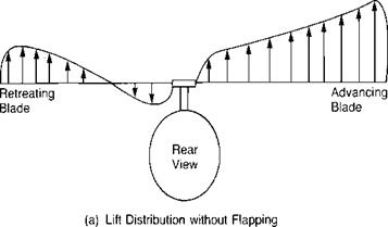
During the early development of the autogiro, Juan de la Cierva tried to obtain structural integrity for his rotor by bracing the blades with landing and flying wires just as the wings of airplanes were braced in those days. On the first attempted takeoff, the aircraft rolled over on its side and smashed the rotor before it had attained flying speed. Cierva rebuilt the machine, but on the next takeoff it again rolled over and smashed the rotor before it had attained flying speed. This action was a mystery to Cierva, since he had flown a rubber-powered model autogiro and had observed no appreciable rolling moment. The model had been built with rattan blade spars and since, in model size, this type of construction was structurally adequate, there was no need for the landing and flying wires that he used on his full-scale rotors. After much thought, Cierva realized that it was the difference between the rigid, wire-braced rotor of the full-scale aircraft and the flexible blades of the model rotor that accounted for the difference in rolling moment. It has already been pointed out that in forward flight, the advancing blade has higher velocities acting on it than the retreating blade. If each blade had the same pitch setting, their angles of attack would be nearly the same, but the difference in velocity would produce more lift on the advancing side than on the retreating side. This would produce an unbalanced rolling moment, as shown in
|
|
|
|
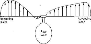
(b) Lift Distribution with Flapping
FIGURE 3.15 Effect of Blade Flapping on Lateral Lift Distribution
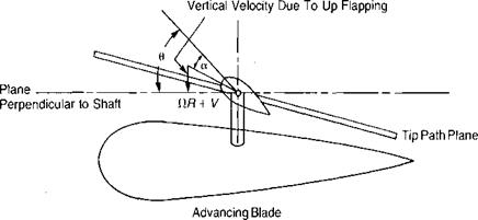
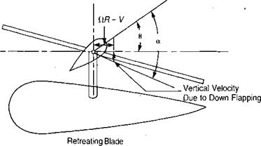
Figure 3.15a, which would be expected to roll the aircraft over. On the model, however, because of the flexibility of the rattan blade spars, the blades could bend up and down. Thus the advancing blade, which initially had high lift, began to accelerate upward. As it was accelerating upward, it was also being rotated toward the nose, where the local velocity was reduced to its mean value, so that no unbalanced lift existed and the blade stopped accelerating. The retreating blade was undergoing a similar experience except that it was accelerating downward as it rotated to a position over the tail. The flapping produced a climbing condition on the advancing blade as shown in Figure 3.16 and thus decreased its angle of attack. The retreating blade, on the other hand, was descending and thus experiencing an increased angle of attack. The rotor came to a flapping equilibrium when the local changes in angle of attack were just sufficient to compensate for the local changes in dynamic pressure. In this equilibrium condition, the rotor was not tilted sideways but was tilted fore and aft as shown in Figure 3.17, and the lift distribution was balanced as shown in Figure 3.15b rather than unbalanced as in Figure 3.15a.
|
|
|
FIGURE 3.16 Change in Angle of Attack Due to Flapping |
|
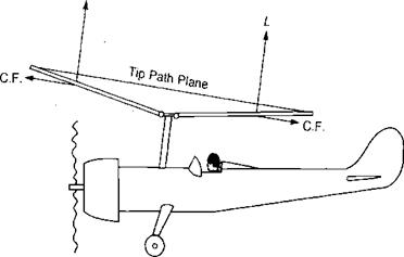
FIGURE 3.17 Autogiro in Level Flight |
When this phenomenon became clear to Cierva, he knew what he had to do: add flexibility to his full-sale rotor. He decided that the simplest solution would be to use a mechanical hinge that would allow the blades to flap and automatically eliminate the rolling moment that had given him such serious problems. The only wires retained were those used to prevent the blades from flapping down too far as the rotor was stopped. In flight, the blades were kept extended by a combination of lift and centrifugal forces, as in Figure 3.17. When such a rotor is established in its stable flapping position, there are no accelerating forces on it causing it to flap with respect to an axis system fixed in the tip path plane. Thus in order that the moments at the hinges are zero, the aerodynamic moment must be a constant around the azimuth and numerically equal to the centrifugal force moment produced by the coning, which is also a constant since the tip path is assumed to lie in a plane. Any change in the distribution of the aerodynamic moments due to changes in flight conditions will force the rotor to seek a new stable flapping position where the aerodynamic and centrifugal moments will again be constant, equal, and opposite around the azimuth.
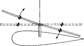
With this technological breakthrough, Cierva was able to fly his autogiro and began a long line of development that has resulted in most present-day helicopters having rotors with flapping hinges. The invention of the flapping hinges did not cure ail of Cierva’s rotor problems, however. He was plagued with high stresses and structural failures in his early blades resulting from moments in the plane of the rotor disc, the so-called inplane moments. These were due to a combination of cyclically varying drag and inertia (or Coriolis) loads. The drag variation was caused by the previously discussed nonuniform aerodynamic environment in which even though the blade lift was made uniform around the azimuth by flapping, the drag was not. The nonuniform inertial loads were the result of the blades obeying a physical law called the law of conservation of momentum, whose effects are familiar to those old enough to remember the swiveling piano stool and the trick of holding a pair of heavy books at arm’s length while being set spinning by a friend. As the books were pulled in toward the body, the spin became faster and faster. The same principle is used by a figure skater to produce a highspeed spin. The law of conservation of momentum states that the product of the moment of inertia and the rate of spin is a constant. As the blade flaps up, its center of gravity moves in toward the spin axis, as shown in Figure 3.18. The same thing happens for the down-flapping blade. This reduces the moment of inertia so each blade tries to speed up. If they are resisted by the inertia of other blades, they will try to bend forward, thus producing inplane bending moments and corresponding stresses in the blade roots. Note that each blade of flapping rotor goes through this cycle twice in a revolution, thus producing two-per-rev—-or 2 P—stresses. Had Cierva’s rotor had only two blades, these stresses would have been minimized since the blades would have acted in unison with nothing to restrain them. As it was, Cierva’s rotor had four blades, and it had problems. He decided that if one hinge in a blade was good, two must be better; so he incorporated vertial hinges such that the blades could move back and forth in the plane of the rotor without generating stresses in the roots. These hinges are now known as lead-lag hinges and, in conjunction with the flapping hinges, produce the
|
|
|
FIGURE 3.18 Inplane Blade Bending Due to Flapping Motion |
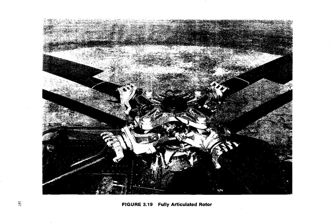
fully articulated rotor systems used on many helicopters today. The lead-lag hinges are important in the study of rotor loads, vibration, and such specialized problems as ground resonance; but they have no effect on performance, stability, or control. For this reason, they will be neglected in the remainder of this book.
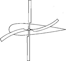
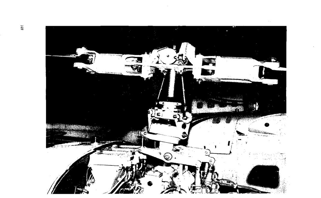
A fully articulated rotor is shown in Figure 3.19. Some designers have elected to put enough structure into the blades and hub that the inplane stresses can be kept to a low and safe level without lead-lag hinges as in the rotor of Figure 3.20 and some designers have even eliminated the flapping hinge by substituting a flexible section of the hub. This latter system is the so-called rigid rotor or hingeless rotor of Figure 3.21, which will later be shown to be equivalent to a hinged rotor with offset flapping hinges.
The 90° lag between the maximum aerodynamic input and the maximum flapping is typical of systems in resonance, and it may be shown that the rotor is a resonating system by the analogy of a mass supported on a spring, as shown in Figure 3.22. The mass will have a characteristic natural frequency at which it will oscillate if it is plucked and then released. The natural frequency will be equal to /k/m rad/sec. If, instead of plucking the mass, a variable-speed electric motor
|
|
|
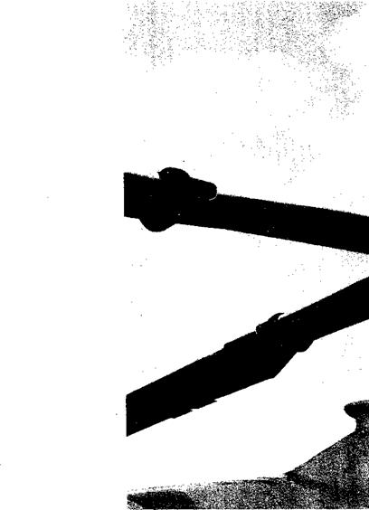
FIGURE 3.20 Teetering Rotor |
|
|
![]() Hingeless Rotor
Hingeless Rotor
 with an unbalanced flywheel is used to excite it at various motor speeds, it will be found that the speed at which the motion of the mass is the greatest will be exactly the same as the natural frequency found by plucking the system. At this speed, it may be said that the mass is in resonance with the exciting frequency.
For a rotating system such as a rotor blade, the natural frequency is given by an equation similar to that for the spring and mass:
where К is the rate of the restoring moment about the flapping hinge in foot pounds per radian of flapping angle, and I is the moment of inertia of the blade about the flapping hinge. The restoring moment is due to the centrifugal force acting though a moment arm which is a function of the flapping angle, p, as shown in Figure 3.23. The centrifugal force acting on a blade element a distance r from the center of rotation is:
AC. F. = Cl2mAr
where m is the mass per running foot. The restoring moment due to this centrifugal force is thus:
AM = AC. F. rp or
AM = nv2wpAr
and the total restoring moment obtained by integration is:
Substituting this into the equation for the natural frequency gives:
This says that the natural frequency of the flapping motion of a blade is equal to its rotational speed no matter what that speed is, and that the blade will always be in resonance with the exciting forces caused by the once-per-revolution unbalance of the aerodynamic forces. (Strictly speaking, this is true only for a blade without hinge offset, but it is nearly true for all blades. See Chapter 7 for the effects of offset.) The blade in resonance will exhibit the characteristic 90° lag between input and response that is inherent in all resonating systems. The result is that the rotor flaps fore and aft rather than laterally in response to unequal dynamic pressure on the advancing and retreating blades. In addition, a small amount of lateral flapping will be generated due to another aerodynamic effect. As the rotor
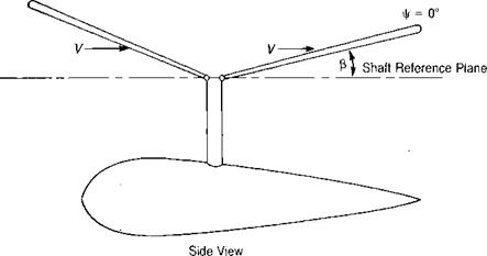
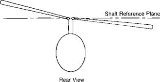
produces lift, it is coned by the combination of lift and centrifugal forces. In forward flight the blade over the nose experiences air coming toward its lower surface, whereas the blade over the tail experiences air approaching it from on top, as shown in Figure 3.24. The result is that the angle of attack on the blade at у = 180° is increased and the angle of attack of the blade at V|/ = 0° is decreased. The rotor compensates for this inequality in the same manner as it did for the nonsymmetric velocity patterns on the advancing and retreating blades: it responds 90° later by tilting up on the retreating side and down on the advancing side. This causes flapping velocities over the nose and over the tail that are exactly enough to compensate for the difference in angle of attack caused by the coning.
The flapping motion may be represented by an infinite Fourier series:
(3 = a0 — als cosvj/ — bls sin vj/ — als cos 2^ — b2s sin 2|/ • • • — и cos — b„s sin n\f
(where j/ is as defined in Figure 3.14.)
|
|
|
FIGURE 3.24 Velocity Orientation Causing Lateral Rotor Tilt |
Only the first three terms will be used in the subsequent analysis since it may be shown using the equations of reference 3.15 that the second and higher harmonics represented by the remaining terms are relatively small and have very little effect on rotor thrust ancj torque. Thus it will be assumed that:
P = a0 — ax^ cos |/ — bls sin |f
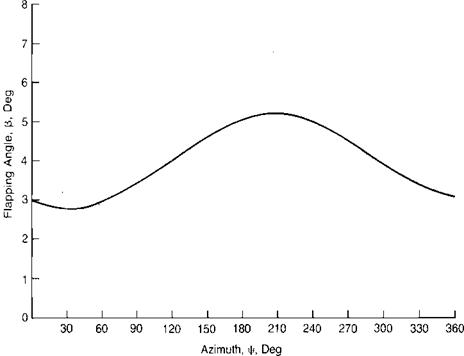
where aQ represents the average value, or coning; aXj is the longitudinal flapping with respect to a plane perpendicular to the shaft defined as positive when the blade flaps down at the tail and up at the nose, and bx is the lateral flapping defined as positive when the blade flaps down on the advancing side and up on the retreating side—the normal condition. For the flapping shown in Figure 3.25, the coefficients are:
я0 = 4.0 ax = 1.0
lS
bx =0.5
lS
|
FIGURE 3.25 Typical Flapping Angle Response |