Flapping motion due to cyclic feathering
The rotor is subjected to a constant feather angle and a feather angle that is varied sinusoidally relative to the hub as expressed by the equation below:
0 = 0o — A1 cos ^ — B1 sin ^ (4.22)
From Equation (4.19) it has already been shown that:
M
P +)2(1 + g)p =_A [4]
If the independent variable is changed from time to blade azimuth angle by means of ^ = )t, then:
|
|
In this scenario lift changes on the blade will arise from two sources: the change in angle of attack caused by the cyclic feathering and the flapping motion itself. It can be shown for an untwisted blade therefore that, since the moment due cyclic feathering is given by:
then the total flapping moment becomes:
![]() (60 — Ay cos ^ — By sin ^)(1 + 2e/3) — (1 — e)(1 + e/3)-jy-
(60 — Ay cos ^ — By sin ^)(1 + 2e/3) — (1 — e)(1 + e/3)-jy-
(4.24)
Thus using Equations (4.23) and (4.24): +Y(1—e)3(1+е/3)н^+(1+є)р=8(0O—Ai cos ^—Bi sin ^)(1—e)2(1+2e/3)
(4.25)
Only the steady state solution is of interest here. Thus if the blade flapping is expressed as:
P = a0 — ay cos ^ — by sin ^
Then solving Equation (4.25) gives:
![Flapping motion due to cyclic feathering Подпись: [є A — nBy ]](/img/3132/image282_0.gif) Y(1 — e)2(1 + 2e/3 + e2 /3)
Y(1 — e)2(1 + 2e/3 + e2 /3)
8(s2 + n2)
, Y(1 — e)2(1 + 2e/3 + e2 /3) , ni
Ь1 =———————— ^+2)————————————- tnAi + ЄВ1]
Y(1 — e)2(1 + 2e/3 + e2 /3)
a0 = 8(ТТЄ) 0O
n = 8(1 — e)3(1 + e/3)
Now consider the case when the hinge offset is zero. Thus є = e = 0 and:
ay = — By by = Ay a0 = Y©0
Once again confirmation of the existence of a 90° phase shift is given since, for an anticlockwise rotating rotor, rearwards disk tilt is caused by an increase in feather over the starboard quarter and starboard disk tilt is generated by an increase in feather over the nose. Returning to the situation with non-zero hinge offset, examination of
the equations for a1 and b1 indicate that cross-coupling will be present. This can be readily appreciated if the case of an increase in B1 is considered; the magnitudes of both a1 and b1 will be affected. The cross-coupling can be expressed as a phase shift, ф, in terms of the azimuth angle between blade feather and blade flap response. For a blade with a uniform mass distribution:
![]() Ши
Ши
and Iyy = -3 (1 – e)2R2
So from Equation (4.19):
mb Xg eR2 3mb (1 – e)eR2 3e
S = Tyy = 2mb(1 – e)2R2 = 2(1 – e)
Therefore:
![]() y(1 – e)4(1 + e/3)
y(1 – e)4(1 + e/3)
12e
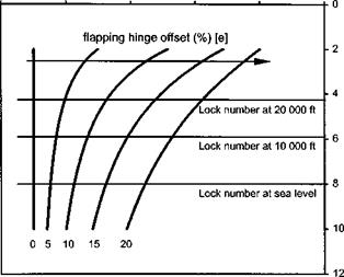
Figure 4.8 shows the variation of ф with hinge offset and Lock number. The amount of cross-coupling, indicated by the reduction in ф from 90° increases with increasing hinge offset and reduces with increases in Lock number.
It should be noted that Lock number is air density dependent and therefore will reduce with altitude. The cross-coupling caused by hinge offset can be removed by mixing the cyclic feather demand such that when the pilot moves the cyclic stick forward, forward disk tilt is the only result. However, it should be appreciated that the mixing, if mechanically engineered, will only be exactly right at a single density altitude. During a ceiling climb, therefore, significant cross-coupling may occur as
PHASE ANGLE (deg) [ф]
100 80 60 40 20 0

indicated on Fig. 4.8 using a sea level Lock number of 8. As the aircraft climbs the flap response will lead its sea level setting. Consequently, for an anticlockwise rotating rotor more and more roll to starboard will result as a nose down pitch demand is made at higher and higher altitude. This effect is called acceleration cross-coupling since it arises from moments generated by the rotor. Rate cross-coupling arising from a rotor under a steady pitch or roll rate will be covered next.


