Integrals of Motion
Force-free motions of spinning rigid bodies have occupied the interest of researchers for centuries, with the Earth as their primary object of scrutiny. Yes, the Earth nutates and precesses, although at such miniscule amounts that our daily lives are unaffected. Astrophysicists, however, earn their living by analyzing and
predicting these phenomena. The Frenchman Poinsot (1834) is particularly well known for his painstakingly geometrical description of the general motions of spinning bodies.
Modem technology has added other applications. Although gyros and spinning rockets are subject to moments and disturbances, much physical insight can be gained by studying their behavior in a force-free environment. Two integrals govern these motions. The angular momentum is constant in the absence of external moments, and the kinetic rotational energy is constant without work being applied to the body.
6.4.3.1 Angular momentum integral. In the absence of external moments, Euler’s law states that the inertial time rate of change of the angular momentum of a body В is zero:
D’lBjj = 0
If integrated in inertial coordinates, we arrive at the first integral of motions
[ig1]1 = [const]7 (6.66)
Note that we had to choose a coordinate system to carry out the integration. Had we picked the body coordinates, the integral of motion would be more complicated:
[lBI]B = – j[QBI]B[lf]Bdt + [ConSt]B
Equation (6.66) is also called the theorem of conservation of angular momentum. In the absence of external stimuli, the angular momentum remains constant and fixed wrt the inertial frame.
6.4.3.2 Energy integral. Without external moments no work is done on the spinning body, and therefore its kinetic energy remains constant, as confirmed by the energy theorem Eq. (6.64). Thus we conclude from Eq. (6.62), disregarding linear kinetic energy and substituting the angular momentum lBB = ІвшВІ, that the energy integral is constant:
2 TBI = іoBIlBBu>BI = QBIlBl = const (6.67)
Because we are dealing with a scalar product, Eq. (6.67) can be evaluated in any allowable coordinate system. Expressing it in body coordinates, which also serve as principal axes, we receive the energy ellipsoid
|
О 0 0 _ |
~0>“ |
||
|
[® 1 ®2 ®з] |
о о |
0)2 |
|
|
о о w4 |
— /]«]+ І2СО 2 + /з®з = 2 TB!
and normalized
![]()
![]() „ .2 ,.2 2
„ .2 ,.2 2
(О і ^3
2TBI/h + 2 TBl/I2 + 2TBl/I3
The energy ellipsoid is the locus of the endpoints of those vectors шві that belong to an energy level TBI. The three semi-axes are
a = y/2TBI/I, b = J2TBI/I2, c = j2TBI/h
Comparison with the MOI ellipsoid Eq. (6.13) establishes the fact that both ellipsoids are similar, i. e., their principal axes are parallel and scaled by the constant factor V2 TBI.
6.4.3.3 Poinsot motions. The two integrals of motion can be used to solve for the movements of spinning force-free bodies. Without the need for calculations, Poinsot has devised a geometrical method that visualizes the motions. For a detailed discussion you should consult Goldstein.2 I will just provide the essentials here and use Fig. 6.18 to explain the geometry.
1) Equation (6.67), with n — lB1 /lBI, defines a plane, whose normal form is шВІп — 2TBI/lg’ = const and which always contains the endpoint of шВІ.
2) Equation (6.66) fixes Ig1 in inertial space. The plane, defined by Eq. (6.67), is fixed in inertial space as well, and is called the invariable plane.
3) Equation (6.68), the energy ellipsoid, is the locus of all endpoints of шВІ.
4) The general motion of a force-free gyro, rotating about a fixed point B, is described by the rolling of the energy ellipsoid on the invariable plane.
Example 6.14 Impulse Control
Problem. A spin-stabilized missile with spin rate o>o and МОЇ I receives an impulsive torque /ив At from its reaction control jet. What is the new direction of the missile and what is the roll rate ф and nutation rate (/?
Solution. Figure 6.19 shows the missile before the impulse is applied. Its spin rate u>o and angular momentum lо are still aligned with the body axis IR. Now the reaction jet fires, and the impulsive torque introduces a nutation of the B axis of the missile (see Fig. 6.20). The new attitude of the missile is centered around the angular momentum vector l, displaced from its original position lо according to Eq.(6.5%) Ъу Al = mBAt. Therefore,
![]()
 |
l = I0 + Ai = h + mB At
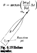 |
The angle between Z0 and l is the change in the mean attitude of the centerline of the missile. It is the nutation angle в, calculated from Eq. (6.59) as
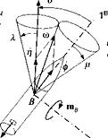
(In an actual application the nutation is reduced to zero by aerodynamic damping). The motion of the missile can be visualized by the body and space cones of Fig. 6.20. The body cone is centered on the Is axis, and the space cone contains the angular momentum vector, which is fixed in space. As the body cone rolls on the space cone, the missile traces its path. The angular velocity vector u> consists of two components, the roll rate of the missile ф and the nutation rate І]. They are calculated from the vector triangle, consisting of the absolute values p, ф, and f] the half-cone angles X and p.
First, we determine X, the angle between the angular momentum and angular velocity vectors. The angular momentum is given by Eq. (6.69) and the angular
![]()
![]()
![]()
![]()

 space
space
cone
velocity vector by ш = I /. The scalar product yields the desired relationship:
![]() A = arccos ■
A = arccos ■
The half-angle of the body cone is /г = 9 — X. From the law of sines, we can now calculate the roll rate
sin A __ _
 Ф = ~r~,—– —cu (6.70)
and the nutation rate
![]() sin(7T — 9)
sin(7T — 9)
The roll rate ф increases with the widening of the space cone, and the nutation rate fj gets larger with the increase of the body cone.
This short excursion into gyrodynamics should give you an appreciation for the “strange” behavior of spinning objects. Their main modes are nutation and precession. Nutation is a fast circular motion of the body axis, whereas precession is a slower movement of the angular velocity vector. I introduced a new term, the kinetic energy of a rigid body TBR. It is a scalar that depends on the body В and an arbitrary reference frame R, consisting of rotational and translational kinetic energy. Flywheels are a good example for storing large amounts of rotational energy. Particularly simple to explain are the dynamics of force-free gyros. Two integrals of motion render Poinsot’s graphical representation of the energy ellipsoid rolling on the invariable plane.
6.5 Summary
This chapter is dominated by Euler’s law. We adopted the viewpoint that it is a basic principle which governs the attitude dynamics quite separately from Newton’s law, although we recognize their kinship. For its formulation three new entities are needed. The moment of inertia is a second-order tensor, real and symmetric, can be diagonalized, and is represented geometrically by the inertia ellipsoid. The angular momentum vector derives from the linear momentum by the multiplication with a moment arm. For aerospace applications, however, it is more likely expressed as the product of the MOI tensor with the angular velocity vector. The externally applied moment or torque is the stimulus for the body dynamics. These are mostly aerodynamic and propulsive moments. Details will be discussed in Part 2.
The modeling techniques for flight dynamics are now completely assembled. You should be able to model the geometry of engagements, express vectors and tensors in a variety of coordinate systems, calculate linear and angular velocities, and derive the translational and rotational equations of motions of aerospace vehicles. I have consistently formulated first the invariant equations, and then expressed them in coordinate systems for computer implementation. We saw no need to deviate from the hypothesis that points and frames can model all entities which arise in flight mechanics. A consistent nomenclature sprang from this premise, enclosing all essential elements of a definition in sub – and superscripts.
You should be prepared now to face the cruel world of simulation, be it in three-, five – or six-DoF fidelity. In Part 2 I give you a running start with detailed examples and code descriptions that are available on the CAD AC CD. Before you proceed, however, I invite you to study one other topic, particularly important for engineering applications: the formulation of perturbation equations. Do not despise the “small” approximations, despite the raw computer power on your desk. Perturbation equations give insight into the dynamics of aerospace vehicles and are essential in the design of control systems.
References
1 Truesdell, C., “Die Entwicklung des Drallsatzes,” Zeitschriftfiir Angewandte Mathematik und Mechanik, Vol. 44, No. 4/5, 1964, pp. 149-158.
2Goldstein, H., Classical Mechanics, Addison Wesley, Longman, Reading, MA, 1965, p. 5,6.
3Mises, R. v., “Anwendungen der Motorrechnung,” Zeitschrift fiir Angewandte Mathematik und Mechanik, Vol. 4, No. 3, 1924, pp. 209-211.
4Grubin, Carl, “On the Generalization of the Angular Momentum Equation,” Journal of Engineering Education, Vol. 51, No. 3, 1960, p. 237.
5Bracewell, R. N., and Garriott, О. K., “Rotation of Artificial Earth Satellites,” Nature Vol. 182, 20 Sept. 1958, pp. 760-762.
6Klein, E, and Sommerfeld, A., Ueber die Theorie des Kreisels, 4 Vols., Teubner, 1910-1922.
7Magnus, K., Kreisel, Theorie und Anwendungen, Springer-Verlag, Berlin, 1971.
8Wrigley, W., Hollister, W., and Denhard, W. G., Gyroscopic Theory, Design and Instrumentation, M. I.T. Press, Cambridge, MA, 1969.
9Draper, C. S., Wrigley, W., and Hovorka, J., Inertial Guidance, Pergamon, New York, 1960.
Problems
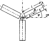
6.1 MOI of helicopter rotor. A three-bladed helicopter rotor revolves in the counterclockwise direction. Each blade has the same dimensions l = length, c — chord, and t = thickness. The mass center Вь of each blade к is displaced from
 |
1B!
the hub’s center R by b. Derive the MOI tensor of the three blades referred to R in helicopter coordinates [I^Bk]B. Assume constant density p of the blades.
6.2 Alternate formulation of axial MOI. The axial MOI /„ about unit vector n of MOI tensor IB is
In = nIBn
or, with the definition of the MOI, summed over all particles і
Show that it can also be expressed as
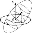 |
where N — E — nn is the planar projection tensor of the plane with normal n [see Eq. (2.25)].
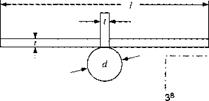
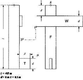
6.3 Mass properties of transport aircraft. For a six-DoF simulation of a transport aircraft, you need rough values for the mass mB and the MOI tensor [IB]B of the total body В referred to the common c. m. C and expressed in body axes ]fi.
(a) Formulate the equations of the individual MOIs [I$]B, [lp]R, Ip]R of wing, fuselage, and tail wrt their respective c. m. and express them in body axes. Afterward calculate their numerical values.
(b) Formulate the equation for the displacement vector L? cr]S of system c. m. C wrt the reference point R at the nose of the aircraft. Afterward calculate its numerical value.
(c) Formulate the displacement vectors swcH, I. v rc IR, І sjc1H for the subsystems c. m. wrt to C. Afterward calculate their numerical values.
(d) Now provide the equations of the vehicle’s total mass properties mB and
[/«?]*•
(e)
Calculate the numerical values of the vehicle’s total mass properties mB and
![]()
 |
Density = 15 kg/tn3
6.4 Change of reference point. A helicopter rotor R has the angular momentum [lf]B wrt the Earth E, referred to the rotor’s c. m. R, and expressed in the helicopter’s body axes lfi. The helicopter flies over the spherical Earth at an altitude h with the velocity [uf ]fi = [їм 0 0]. What is the rotor’s angular momentum llRE]B wrt the center of Earth El
6.5 Total angular momentum of a helicopter. The airframe of a helicopter В with mass mB has three rotary devices affixed: the main rotor with mass mM and MOI /^; the turbine mr, lTT and the tail rotor mR, /{$. While the helicopter is hovering, you are to calculate the total angular momentum [l^1]8 of the helicopter wrt the inertial frame and referred to the common c. m. C in helicopter coordinates ]fi. The individual MOI’s and angular velocities are in air-frame coordinates H:
|
mB = |
і ° |
0 I М2 |
1 О О |
^ ° 1___ |
0 hi |
f——- О О |
|
|
_ 0 |
0 |
1мъ_ |
_ 0 |
0 |
hi |
|
hi |
0 |
0 |
|
0 |
1r2 |
0 |
|
0 |
0 |
hi |
ШМВ]В = [0 о [ЮТВ]В = [(0т 0 0], [coKBR = [0 wR 0]
|
|
6.6 Force-free body parameters. A force-free body В spins around its c. m. В with [of’1]1 = [1 0 2] rad/s, having an MOI of [/f ]fi = [diag(3, 2, 2)] kgm2. What are its angular momentum [If7]7 and kinetic energy TB,1
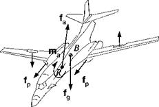
6.7 Forces and moments. А В1 aircraft is subject to several forces and moments. The aerodynamic forces fa and ma are referred to reference point R, and the propulsive thrust of the right and left engines are / respectively. To make a right turn, the pilot generates with the ailerons a couple mc. What are the resultant force / and moment /яв wrt the aircraft mass center B1 Introduce the necessary displacement vectors to make the equations self-defining.
|
|
6.8 Symmetric gyro. A symmetric gyro executes motions characterized by the condition that three vectors always are coplanar: the angular momentum lg, the angular velocity шВІ, and the unit vector b i of the symmetry axis .Use the following special components to verify this statement:
|
~h |
0 |
O’ |
~0~ |
|
|
0 |
h |
0 |
, [ЬЛВ = |
0 |
|
_0 |
0 |
h. |
_1_ |
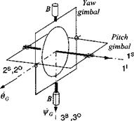
6.9 Free gyro. A two-axes gyro has two free gimbals. The inner gimbal supports the spin axis, and the outer gimbal rotates freely in the bearings attached to the vehicle В. The gimbal pitch angle 6(, and yaw angle фс are indicated by their angular rate vectors 6 a and ф a ■
(a) Derive the relationship between the gimbal angles and Euler angles of the vehicle. Procedure: The spin axis s is parallel to the l5 axis and to the I’ axis (assuming ideal gyro). Express its body coordinates both in inertial ]7 and inner gimbal coordinates ]5:
(И® =)[Т]В7И7 = [T]BS[s]s
|
|
where [T]BI contains the Euler angles and [TBS the gimbal angles. By comparing equal elements, the desired relationship is obtained.
(b) Derive the differential equations of the gimbal angles 6G and i/rc as functions of the body rates fwBIB = [p q r. Procedure: The angular velocity vector uisfi of the inner gimbal frame S wrt the body frame В is expressed in terms of the inertial body rates шт by the following steps. Take the rotational derivative of the spin axis s wrt the body frame В and transform it to the inner gimbal S and also to the inertial frame I:
(DBs =)Dss + SlSBs = D’s + flIBs
Because s is fixed in both the В and I frames, both derivatives are zero, and you get
nsfls = fl! Bs
For actual calculations it is most convenient to use the outer gimbal coordinates і о
[Й*ТМ° = [П“]0М0
and express the spin axis [.s]5 in inner gimbal coordinates and the body rates Q. ri’B in body coordinates then reversing the angular velocities
= [Т]ов[^в/]с,[Г]іі5[і]5
The result is
Oc — q COS l/fG + p sin fG
фа = r + (q sin i/fG — p cos ijrG) tan 9C
Both methods can be used to calculate the gimbal angles. What are their respective advantages and disadvantages?
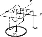 |
6.10 Gyro mass unbalance. The spin axis of a gimbaled gyro is subject to a mass unbalance Am, located at a distance b from the c. m. The resulting moment is constant in the inner gimbal (precession frame P). Determine the precession angular velocity rp if the spin velocity ф and the МОЇ I of the rotor are given.
6.11 Change of reference point for kinetic energy. The kinetic energy Tm of a rigid body finds its simplest expression if its c. m. В is used [see Eq. (6.62)]. If an arbitrary point B of the body is introduced as reference point, show that the kinetic energy is calculated from the formula
where mBVgt flBRs bb, is the supplementary term required because B is not the c. m.
6.12 Bearing loads on turbine during pull-up. The Mirage jet fighter has a single turbine engine T located near the c. m. В of the aircraft B. As it pulls up, you are to calculate the forces and moments that the bearings have to support. The pull-up occurs in the vertical plane at a radius R and aircraft velocity Vg.
(a) Derive in invariant form the bearing forces counteracting centrifugal and gravity accelerations and the bearing torque opposing the gyroscopic moment.
(b)
 |
Express the bearing forces and moments in aircraft body coordinates while the Mirage is at the bottom of its pull-up. Besides R and [йд]в = [ V 0 0], the following parameters are given for the turbine: mass mT MOI [IP]B = [diag(/i, h, /3)]; and angular velocity coTnB = [w 0 0]. You can assume that the two c. m. T and В coincide.
6.13 Control moment gyros of the Hubble telescope. The Hubble space telescope B0 is stabilized by three control moment gyros (CMG) Bt, B2, and B3. The
CMG mass centers have the same distance x from the center So and are equally spaced, starting with gyro #1 aligned with the 1B" axis of the telescope. The directions of the spin axes are shown in the accompanying figure. The following quantities are given: mass of telescope, m§ mass of one CMG, m; spin MOI of CMG, ls transverse MOI of CMG, /; angular rate of GMC wrt Bo, w; distance of CMG from Bo, x; MOI of telescope,
![]() 7o 0 О /о 0 0
7o 0 О /о 0 0
velocity of telescope wrt inertial frame, [v^J1 = [0 vq 0]; angular velocity of telescope wrt inertial frame, [ojBnI’ = [0 0 ®o]-
(a) For the cluster к — 0, 1,2,3, determine in tensor format the linear momentum p ^ B, the MOI / ^, the kinetic energy T1 й‘/, and angular momentum l 1.
(b) Express the four quantities in the telescope’s coordinates [R" using the TM
 |
COS l/f sin xjf 0 —sin іfr cos іft 0 0 0 1
 |
6.14 Shuttle pitch equations during release of satellite. Derive the pitch attitude equations of the space shuttle Bo as it launches a satellite B. Assume that the release is parallel and in the opposite direction of the space shuttle’s 3 axis. The satellite’s displacement vector from the shuttle’s c. m Bo is [.v/;, l/f" = [—a 0 rj], where a is a positive constant and r}(t ) a known function of t. The mass of the manipulator’s arm can be neglected, and the satellite treated as a particle with mass mHi. The mass properties of the shuttle are mB" and [/^"]B" = [diag(/i, I2, h)]. Determine the differential equation of motion of the shuttle’s pitch angular velocity о>и‘]І B" = [0 q 0]. All external forces and moments can be neglected.
6.15 Missile pitch equations with swiveling motor. The attitude of a missile Bo is controlled by its swiveling rocket engine Bi with thrust 1D] = [T 0 0] and known swivel angle S(t). Neglecting all other forces and moments, determine the differential equation that governs the pitch angular velocity |ojB(|/ |B° = [0 ry 0] of the missile. The mass properties are given:
m B" • [ / a" ] B° = di ag( /!, /2, /3)
тв[ів’]В’ =diag(Jb J2, h)
 |
and assumed constant.
Solution 6.14
h(mB’ + mB°)
Solution 6.15
![]()

![]()
 |
+12 + L2 + 2IL cos 5(0 M


