Semi-rigid rotors
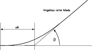
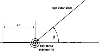
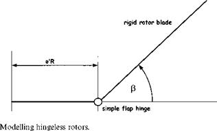
The flap behaviour of a semi-rigid rotor can be modelled by approximating the rotor system to one with a hinge offset and a spring force. The size of the hinge offset, now referred to as the effective hinge offset, is chosen so that blade flap mode shape equates to the real blade under out-of-plane bending, see Fig. 4.18. Now the basic flapping equation is given by Equation (4.19) as:
Iyy P + ) 2 (Iyy + mb Xg eR2 )P = MA
|
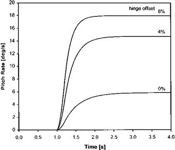
Fig. 4.16 Effect of hinge offset on pitch rate response. |
|
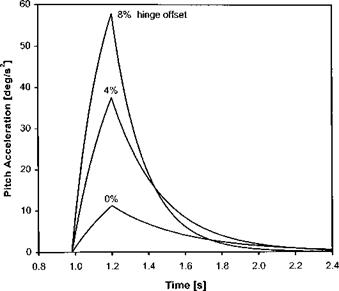
Fig. 4.17 Effect of hinge offset on pitch acceleration. |
The spring produces a restoring moment proportional to the flap angle, thus Equation (4.19) becomes:
Iyy p + n2(Iyy + mb Xg eR2 )p + KpP = MA (4.37)
|
In order to determine the effect of this extra moment consider the case when the blade is disturbed in the flapping sense whilst in the hover. As before the aerodynamic moment is given, from Equation (4.20), by:
Мк у
~T =-у(1 – e)3(1 + e/3)np
lyy 8
Thus substituting into Equation (4.37):
Iyy p + 8(1 – e)3(l + e/3)Iyy )p + Q.Iyy + mb Xg eR2 )p + KpP = 0
or:
|
mb Xg eR[5] [6] [7] |
p + n )p + )2(1 + s + k)P = 0 where:
Taking Laplace transforms:
^2 + n )s + )2(1 + s + k) = 0
Comparing with the standard second-order characteristic equation:
The above equations indicate that the presence of the spring increases the natural frequency and reduces the flap damping. This is exactly the same effect as caused by increases in hinge offset, therefore a hingeless rotor may be adequately represented by a fully articulated rotor with a hinge offset greater than the geometric equivalent, as in Fig. 4.18.


