
Our heavyweight helicopter equal in the world does not have
In Rostov started production of the most load-lifting rotary-wing car The Russian holding «Helicopt[...]

Everything about aircrafts and helicopters. News and events in aviation worldwide. Civil, transportation, military helicopters and airplanes.

Everything about aircrafts and helicopters. News and events in aviation worldwide. Civil, transportation, military helicopters and airplanes.

Everything about aircrafts and helicopters. News and events in aviation worldwide. Civil, transportation, military helicopters and airplanes.

Everything about aircrafts and helicopters. News and events in aviation worldwide. Civil, transportation, military helicopters and airplanes.


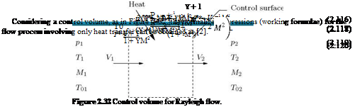
In the section on flow with area change, the process was considered to be isentropic with the assumption that the frictional and energy effects were absent. In Fanno line flow, only the effect of wall friction was taken into account in the absence of area change and energy effects. In the present section, the processes involving change in the stagnation temperature or the stagnation enthalpy of a gas stream, which flows in a frictionless constant area duct are considered. From a one-dimensional point of view, this is yet another effect producing continuous changes in the state of a flowing stream and this factor is called energy effect, such as external heat exchange, combustion, or moisture condensation. Though a process involving simple stagnation temperature (Tq) change is difficult to achieve in practice, many useful conclusions of practical significance may be drawn by analyzing the process of simple TQ-change. This kind of flow involving only TQ-change is called Rayleigh type flow.
Working Formulae for Rayleigh Type Flow
Consider the flow of a perfect gas through a constant-area duct without friction, shown in Figure 2.32.
2.13
 |
Summary
Gases and liquids are generally termed fluids. Under dynamic conditions, the nature of governing equations is the same for both gases and liquids.
Fluid may be defined as a substance which will continue to change shape as long as there is a shear stress present, however small it may be.
Pressure may be defined as the force per unit area which acts normal to the surface of any object which is immersed in a fluid. For a fluid at rest, at any point the pressure is the same in all directions. In stationary fluids the pressure increases linearly with depth. This linear pressure distribution is called hydrostatic pressure distribution.
When a fluid is in motion, the actual pressure exerted by the fluid in the direction normal to the flow is known as the static pressure. The pressure which a fluid flow will experience if it is brought to rest,
isentropically, is termed total pressure. The total pressure is also called impact pressure. The total and static pressures are used for computing flow velocity.
The total number of molecules in a unit volume is a measure of the density p of a substance. It is expressed as mass per unit volume, say kg/m3. Mass is defined as weight divided by acceleration due to gravity. At standard atmospheric temperature and pressure (288.15 K and 101325 Pa, respectively), the density of dry air is 1.225 kg/m3.
The property which characterizes the resistance that a fluid offers to applied shear force is termed viscosity. This resistance, unlike for solids, does not depend upon the deformation itself but on the rate of deformation.
Maxwell’s definition of viscosity states that:
“the coefficient of viscosity is the tangential force per unit area on either of two parallel plates at unit distance apart, one fixed and the other moving with unit velocity.”
Newton’s law of viscosity states that “ the stresses which oppose the shearing of a fluid are proportional to the rate of shear strain,” that is, the shear stress т is given by:
Fluids which obey the above law of viscosity are termed Newtonian fluids. Some fluids such as silicone oil, viscoelastic fluids, sugar syrup, tar, etc. do not obey the viscosity law given by Equation (2.3) and they are called non-Newtonian fluids.
For air the viscosity coefficient is expressed as:
where T is in kelvin.
The kinematic viscosity coefficient is a convenient form of expressing the viscosity of a fluid. It is formed by combining the density p and the absolute coefficient of viscosity u, according to the equation:
The kinematic viscosity coefficient v is expressed as m2/s, and 1 cm2/s is known as stoke.
The kinematic viscosity coefficient is a measure of the relative magnitudes of viscosity and inertia of the fluid.
The change in volume of a fluid associated with change in pressure is called compressibility.
The specific heats at constant volume and constant pressure processes, respectively, are designated by cv and cp. The definitions of these quantities are the following:
where u is internal energy per unit mass of the fluid, which is a measure of the potential and more particularly the kinetic energy of the molecules comprising the gas. The specific heat cv is a measure of the energy-carrying capacity of the gas molecules. For dry air at normal temperature, cv = 717.5 J/(kg K).
The specific heat at constant pressure is defined as:
![]() dh dT )
dh dT )
p
The ratio of specific heats:
is an important parameter in the study of high-speed flows. This is a measure of the relative internal complexity of the molecules of the gas.
Liquids behave as if their free surfaces were perfectly flexible membranes having a constant tension a per unit width. This tension is called the surface tension. It is important to note that this is neither a force nor a stress but a force per unit length.
Basically two treatments are followed for fluid flow analysis. They are the Lagrangian and Eulerian descriptions. Lagrangian method describes the motion of each particle of the flow field in a separate and discrete manner.
If properties and flow characteristics at each position in space remain invariant with time, the flow is called steady Bow. A time-dependent flow is referred to as unsteady Bow.
The rate of change of a property measured by probes at fixed locations are referred to as local rates of change, and the rate of change of properties experienced by a material particle is termed the material or substantive rates of change.
For a fluid flowing with a uniform velocity Vx>, it is possible to write the relation between the local and material rates of change of property n as:
dn Dn dn dt ~ Dt – a?
when n is the velocity of a fluid particle, DV/Dt gives acceleration of the fluid particle and the resultant equation is:
This is known as Euler’s acceleration formula.
Pathline may be defined as a line in the flow field describing the trajectory of a given fluid particle. Streakline may be defined as the instantaneous loci of all the fluid elements that have passed the point of injection at some earlier time.
Streamlines are imaginary lines, in a fluid flow, drawn in such a manner that the flow velocity is always tangential to it.
In modern fluid flow analysis, yet another graphical representation, namely timeline is used. When a pulse input is periodically imposed on a line of tracer source placed normal to a flow, a change in the flow profile can be observed. The tracer image is generally termed timeline.
In the range of engineering interest, four basic laws must be satisfied for any continuous medium. They are: [1]
• Conservation of energy (first law of thermodynamics).
• Increase of entropy principle (second law of thermodynamics).
In addition to these primary laws, there are numerous subsidiary laws, sometimes called constitutive relations, that apply to specific types of media or flow processes (for example, equation of state for perfect gas, Newton’s viscosity law for certain viscous fluids, isentropic and adiabatic process relations are some of the commonly used subsidiary equations in flow physics).
A control mass system is an identified quantity of matter, which may change shape, position, and thermal condition, with time or space or both, but must always entail the same matter.
A control volume is a designated volume in space, and the boundary of this volume is known as control surface. The amount and identity of the matter in the control volume may change with time, but the shape of the control volume is fixed, that is, the control volume may change its position in time or space or both, but its shape is always preserved.
The analysis in which large control volumes are used to obtain the aggregate forces or transfer rates is termed integral analysis. When the analysis is applied to individual points in the flow field, the resulting equations are differential equations, and the method is termed differential analysis.
For air at normal temperature and pressure, the density p, pressure p and temperature T are connected by the relation p = pRT, where R is a constant called gas constant. This is known as the thermal equation of state. An ideal gas is frictionless and incompressible. The perfect gas has viscosity and can therefore develop shear stresses, and it is compressible according to state equation.
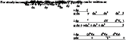
The basic governing equations for an incompressible flow are the continuity and momentum equations. For steady incompressible flow, the continuity equation in differential form is:
These equations are generally known as Navier-Stokes equations.
Boundary layer thickness S may be defined as the distance from the wall in the direction normal to the wall surface, where the fluid velocity is within 1% of the local main stream velocity. It may also be defined as the distance S, normal to the surface, in which the flow velocity increases from zero to some specified value (for example, 99%) of its local main stream flow velocity.
Displacement thickness S* may be defined as the distance by which the boundary would have to be displaced if the entire flow fields were imagined to be frictionless and the same mass flow is maintained at any section.
The momentum thickness в and energy thickness Se are other (thickness) measures pertaining to boundary layer. They are defined mathematically as follows:
Transition point may be defined as the end of the region at which the flow in the boundary layer on the surface ceases to be laminar and becomes turbulent.
Separation point is the position at which the boundary layer leaves the surface of a solid body. If the separation takes place while the boundary layer is still laminar, the phenomenon is termed laminar separation. If it takes place for a turbulent boundary layer it is called turbulent separation.
Circulation Г, is defined as the line integral of velocity vector between any two points (to define rotation of the fluid element) in a flow field. By definition:
Circulation per unit area is known as vorticity f:
Z = Г/A
In vector form, Z becomes:
For a two-dimensional flow in xy-plane, vorticity Z becomes:
![]() dVy dVx
dVy dVx
dx dy ’ where Zz is the vorticity about the z-direction, which is normal to the flow field. Likewise, the other components of vorticity about x – and y-directions are:
![]() dVz
dVz
Zx = ~T dy
If Z = 0, the flow is known as irrotational flow. Inviscid flows are basically irrotational flows.
In terms of stream function ф, the velocity components of a two-dimensional incompressible flow are given as:
![]() дф
дф
Vx = —, v„ = –
x dy y
If the flow is compressible the velocity components become:
For irrotational flows (the fluid elements in the field are free from rotation), there exists a function ф called velocity potential or potential function. For a steady two-dimensional flows, ф must be a function of two space coordinates (say, x and y). The velocity components are given by:
We can relate f and ф as:
|
df |
дф |
df |
дф |
|
dy |
dx ’ |
dx |
dy |
These relations between stream function and potential function are the famous Cauchy-Riemann equations of complex-variable theory.
Potential flow is based on the concept that the flow field can be represented by a potential function ф such that:
This linear partial differential equation is popularly known as Laplace equation. All inviscid flows must satisfy the irrotationality condition:
For two-dimensional incompressible flows, the continuity equation is:
![]() dvx dVy
dvx dVy
— + — dx dy
In terms of the potential function ф, this becomes:
d2ф д2ф
dx2 + dy2
that is:
V2ф — 0,
![]()
This linear equation is the governing equation for potential flows.
For potential flows, the Navier-Stokes equations reduce to:
![]()
These are known as Euler’s equations.
• Among the graphical representation concepts namely, the pathline, streakline and streamline, only the first two are physical, and the concept of streamline is only hypothetical. But even though imaginary, the streamline is the only useful concept, because it gives a mathematical representation for the flow field in terms of stream function ф, with its derivatives giving the velocity components.
• The fundamental solutions of Laplace equation forms the basis for both experimental and computation flow physics. The basic solutions for the Laplace equation are the uniform flow, source, sink and free or potential vortex. These solutions being potential, can be superposed to get the mathematical functions representing any practical geometry of interest.
Source is a potential flow field in which flow emanating from a point spreads radially outwards. Sink is potential flow field in which flow gushes towards a point from all radial directions.
The velocity potential for a two-dimensional source of strength q becomes:
In a similar manner as above, the stream function for a source of strength q can be obtained as:
A simple or free vortex is a flow field in which the fluid elements simply move along concentric circles, without spinning about their own axes. That is, the fluid elements have only translatory motion in a free vortex. In addition to moving along concentric paths, if the fluid elements spin about their own axes, the flow is termed forced vortex. For a simple vortex:
The stream function for a simple vortex is:
A doublet or a dipole is a potential flow field due to a source and sink of equal strength, brought together in such a way that the product of their strength and the distance between them remain constant. The velocity potential for a doublet is:
|
m |
( x |
|
фо = —- |
^x2 + y2 J |
|
ф° 2п |
The stream function for a doublet is:
m y
fo = 2n lx2 + y2
The stream function for the flow due to the combination of a source of strength q at the origin, immersed in a uniform flow of velocity Vx, parallel to x-axis is:
f = Vx r sin в + в.
2n
The streamline passing through the stagnation point S is termed the stagnation streamline. The stagnation streamline resembles a semi-ellipse. This shape is popularly known as Rankine ‘s half-body.
The stream function and potential function of the flow past a cylinder can be expressed as:
The nondimensional pressure distribution over the surface of the cylinder is given by:
The symmetry of the pressure distribution in an irrotational flow implies that “a steadily moving body experiences no drag" This result, which is not true for actual (viscous) flows where the body experiences drag, is known as d’Alembert’s paradox.
• The positive limit of +1 for Cp, at the forward stagnation point, is valid for all geometries and for both potential and viscous flow, as long as the flow speed is subsonic.
• The limiting minimum of —3, for the Cp over the cylinder in potential flow, is valid only for circular cylinder. The negative value of Cp can take values lower than —3 for other geometries. For example, for a cambered aerofoil at an angle of incidence can have Cp as low as —6.
There is no net force acting on a circular cylinder in a steady irrotational flow without circulation. It can be shown that a lateral force identical to a lift force on an aerofoil, results when circulation is introduced around the cylinder.
The location forward and rear stagnation points on the cylinder can be adjusted by controlling the magnitude of the circulation Г. The circulation which positions the stagnation points in proximity, as shown in Figure 2.19(b) is called subcritical circulation, the circulation which makes the stagnation points to coincide at the surface of the cylinder, as shown in Figure 2.19(c), is called critical circulation, and the circulation which makes the stagnation points to coincide and take a position outside the surface of the cylinder, as shown in Figure 2.19(d), is called supercritical circulation.
For a circular cylinder in a potential flow, the only way to develop circulation is by rotating it in a flow stream. Although viscous effects are important in this case, the observed pattern for high rotational speeds displays a striking similarity to the ideal flow pattern for Г > 4naVx. When the cylinder rotates at low speeds, the retarded flow in the boundary layer is not able to overcome the adverse pressure gradient behind the cylinder. This leads to the separation of the real (actual) flow, unlike the irrotational flow
which does not separate. However, even in the presence of separation, observed speeds are higher on the upper surface of the cylinder, implying the existence of a lift force.
A second reason for a rotating cylinder generating lift is the asymmetry to the flow pattern, caused by the delayed separation on the upper surface of the cylinder. The asymmetry results in the generation of the lift force. The contribution of this mechanism is small for two-dimensional objects such as circular cylinder, but it is the only mechanism for the side force experienced by spinning three-dimensional objects such as soccer, tennis and golf balls. The lateral force experienced by rotating bodies is called the Magnus effect. The horizontal component of the force on the cylinder, due to the pressure, in general is called drag. For the cylinder, shown in Figure 2.20, the drag given by: /»2п
![]() I pr=a a cos в dd.
I pr=a a cos в dd.
0
It is interesting to note that the drag is equal to zero. It is important to realize that this result is obtained on the assumption that the flow is inviscid. In real (actual or viscous) flows the cylinder will experience a finite drag force acting on it due to viscous friction and flow separation.
We are familiar with the fact that the viscosity produces shear force which tends to retard the fluid motion. It works against inertia force. The ratio of these two forces governs (dictates) many properties of the flow, and the ratio expressed in the form of a nondimensional parameter is known as the famous Reynolds number, ReL:
The Reynolds number plays a dominant role in fluid flow analysis. This is one of the fundamental dimensionless parameters which must be matched for similarity considerations in most of the fluid flow analysis. At high Reynolds numbers, the inertia force is predominant compared to viscous forces. At low Reynolds numbers the viscous effects predominate everywhere. Whereas, at high Re the viscous effects confine to a thin region, just adjacent to the surface of the object present in the flow, and this thin layer is termed boundary layer.
Reynolds number is basically a similarity parameter. It is used to determine the laminar and turbulent nature of flow.
• Lower critical Reynolds number is that Reynolds number below which the entire flow is laminar.
• Upper critical Reynolds number is that Reynolds number above which the entire flow is turbulent.
• Critical Reynolds number is that at which the flow field is a mixture of laminar and turbulent flows.
When a body moves in a fluid, it experiences forces and moments due to the relative motion of the flow taking place around it. The force on the body along the flow direction is called drag.
The drag is essentially a force opposing the motion of the body. Viscosity is responsible for a part of the drag force, and the body shape generally determines the overall drag. The drag caused by the viscous effect is termed the frictional drag or skin friction. In the design of transport vehicles, shapes experiencing minimum drag are considered to keep the power consumption at a minimum. Low drag shapes are called streamlined bodies and high drag shapes are termed bluffbodies.
Drag arises due to (a) the difference in pressure between the front and back regions and (b) the friction between the body surface and the fluid. Drag force caused by the pressure imbalance is known as pressure drag, and (b) the drag due to friction is known as skin friction drag or shear drag.
The location where the flow leaves the body surface is termed separation point. For flow past a cylinder, there are two separation points on either side of the horizontal axis through the center of the cylinder. The
separated flow is chaotic and vortex dominated. The separated flow behind an object is also referred to as wake. Depending on the Reynolds number level, the wake may be laminar or turbulent. An important characteristics of the separated flow is that it is always unsymmetrical, even for laminar separation.
The friction between the surface of a body and the fluid causes viscous shear stress and this force is known as skin friction drag. Wall shear stress т at the surface of a body is given by:
A body for which the skin friction drag is a major portion of the total drag is termed streamlined body. A body for which the pressure (form) drag is the major portion is termed bluff body. Turbulent boundary layer results in more skin friction than a laminar one.
The turbulence level for any given flow with a mean velocity U is expressed as a turbulence number n, defined as:
„ fr2 ~2 ~
![]() V u + v + w
V u + v + w
3U
“A laminar Bow is an orderly Bow in which the fluid elements move in an orderly manner such that the transverse exchange of momentum is insignificant"
and
“A turbulent Bow is a three-dimensional random phenomenon, exhibiting multiplicity of scales, possessing vorticity and showing very high dissipation."
Flow through pipes is driven mostly by pressure or gravity or both. In the functional form, the entrance length can be expressed as:
Le = f (p, V, d, g)
For laminar flow, the accepted correlation is:
At the critical Reynolds number Rec = 2300, for pipe flow, Le = 138d, which is the maximum development length possible.
For turbulent flow the boundary layer grows faster, and Le is given by the approximate relation:
The pipe head loss is given by:
This is called the Darcy-Weisbach equation, valid for flow through ducts of any cross-section.
Exercise Problems
![]() The turbulence number of a uniform horizontal flow at 25 m/s is 6. If the turbulence is isotropic, determine the mean square values of the fluctuations.
The turbulence number of a uniform horizontal flow at 25 m/s is 6. If the turbulence is isotropic, determine the mean square values of the fluctuations.
[Answer: 6.75 m2/s2]
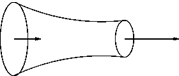
Flow through the convergent nozzle shown in Figure 2.33 is approximated as one-dimensional. If the flow is steady will there be any fluid acceleration? If there is acceleration, obtain an expression for it in terms of volumetric flow rate Q, if the area of cross-section is given by A(x) = e-x.
Answer: (
 — X
— X
3. Atmospheric air is cooled by a desert cooler by 18°C and sent into a room. The cooled air then flows through the room and picks up heat from the room at a rate of 0.15 °C/s. The air speed in the room is 0.72 m/s. After some time from switching on, the temperature gradient assumes a value of 0.9 °C/m in the room. Determine dT/dt at a point 3 m away from the cooler.
[Answer: – 0.498 °C/s]
4. For proper functioning, an electronic instrument onboard a balloon should not experience temperature change of more than ± 0.006 K/s. The atmospheric temperature is given by:
T = (288 – 6.5 x 10⁻³ z) (2 – е-0іш) K,
where z is the height in meters above the ground and t is the time in hours after sunrise. Determine the maximum allowable rate of ascent when the balloon is at the ground at t = 2 hr.
[Answer: 1.12 m/s]
5.
 |
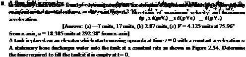
Flow through a tube has a velocity given by:
Cross-sectional area Ai
Cross-sectional area A2
Figure 2.34 A tank on an elevator moving up.
where R is the tube radius and umax is the maximum velocity, which occurs at the tube centerline. (a) Find a general expression for volume flow rate and average velocity through the tube, (b) compute the volume flow rate if R = 25 mm and umax = 10 m/s, and (c) compute the mass flow rate if p = 1000 kg/m3.
Answer: (a) — umaxnR2, -umax, (b) 0.00982m3/s, (c) 9.82kg/s.
6. A two-dimensional velocity field is given by:
 |
V = (x – y2) i + (xy + 2y) j
V = 3xi + 4y j — 5tk.
(a) Find the velocity at position (10,6) at t = 3 s. (b) What is the slope of the streamlines for this flow at t = 0 s? (c) Determine the equation of the streamlines at t = 0 up to an arbitrary constant. (d) Sketch the streamlines at t = 0.
[Answer: (a) V = (30 i + 24 j — 15 k) m/s, (b) 4y/3x, (c) y = | x + c, where c is an arbitrary constant, (d) At t = 0, the streamlines are straight lines at an angle of 38.66° to the x-axis]
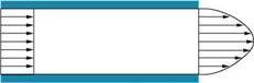
10. For the fully developed two-dimensional flow of water between two impervious flat plates, shown in Figure 2.36, show that Vy = 0 everywhere.
![]()
|
|
|
|
|
|
|
11. ![]() Water enters section 1 at 200 N/s and exits at 30c Section 1 has a laminar velocity profile u = um1 1
Water enters section 1 at 200 N/s and exits at 30c Section 1 has a laminar velocity profile u = um1 1
/ r 1/7
u = um2 1 — .If the flow is steady and incompressible (water), find the maximum velocities
um1 and um2 in m/s. Assume uav = 0.5 um, for laminar flow, and uav = 0.82 um, for turbulent flow.
[Answer: 5.2 m/s, 8.79 m/s]
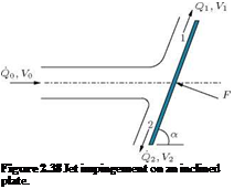
12. Consider a jet of fluid directed at the inclined plate shown in Figure 2.38. Obtain the force necessary to hold the plate in equilibrium against the jet pressure. Also, obtain the volume flow rates Q1 and Q2 in terms of the incoming flow rate Q0. Assume that V0 = V1 = V2 and the fluid is inviscid.
 |
Answer: pVoQ0sin a, Qi = ~^ (1 + cos a), Q2 = ~^ (1 — cos a)
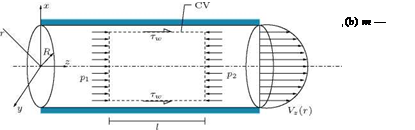
13. Consider a laminar fully developed flow without body forces through a long straight pipe of circular cross-section (Poiseuille flow) shown in Figure 2.39. Apply the momentum equation and show that:
_ P1 – P2 r Trz = l 2′
Assuming (p1 — p2) /l = constant, obtain the velocity profile using the relation:
![]() Trz — M
Trz — M
[Answer: V— (r2 — r2)
![]()
 |
![]()
![]()
 |
A liquid of density p and viscosity m flows down a stationary wall, under the influence of gravity, forming a thin film of constant thickness h, as shown in Figure 2.40. An up flow of air next to the film exerts an upward constant shear stress т on the surface of the liquid layer, as shown in the figure. The pressure in the film is uniform. Derive expressions for (a) the film velocity Vy as a function of y, p, m, h and т, and (b) the shear stress т that would result in a zero net volume flow rate in the film.
У
Figure 2.40 Flow down a stationary wall.
15. Show that the head loss for laminar, fully developed flow in a straight circular pipe is given by:

64 L Vi
Re D 2g ’
where Re is the Reynolds number defined as (pVavD) /д.
16.
A horizontal pipe of length L and diameter D conveys air. Assuming the air to expand according to the law р/р = constant and that the acceleration effects are small, prove that:
where m is the mass flow rate of air through the pipe, f is the average friction coefficient, and 1 and 2 are the inlet and discharge ends of the pipe, respectively.
17. In the boundary layer over the upper surface of an airplane wing, at a point A near the leading edge, the flow velocity just outside the boundary layer is 250 km/hour. At another point B, which is downstream of A, the velocity outside the boundary layer is 470 km/hour. If the temperature at A is 288 K, calculate the temperature and Mach number at point B.
[Answer: 281.9 K, 0.388]
18. A long right circular cylinder of diameter a meter is set horizontally in a steady stream of velocity u m/s and made to rotate at an angular velocity of ю radians/second. Obtain an expression in terms of ю and u for the ratio of pressure difference between the top and bottom of the cylinder to the dynamic pressure of the stream.
8аю’
Answer: —
u
19. The velocity and temperature fields of a fluid are given by:
V = xi + (by + 3f2 y) j + 12 k
T = x + y2z + 5t.
Find the rate of change of temperature recorded by a floating probe (thermocouple) when it is at 3 i + 5 j + 2 k at time t = 2 units.
20. A parachute of 10 m diameter when carrying a load W descends at a constant velocity of 5.5 m/s in atmospheric air at a temperature of 18° and a pressure of 105 Pa. Determine the load W if the drag coefficient for the parachute is 1.4.
[Answer: 1.991 kN]
References
1. Heiser, W. H. and Pratt, D. T., Hypersonic Air Breathing Propulsion, AIAA Education Series, 1994.
2. Rathakrishnan, E., Applied Gas Dynamics, John Wiley & Sons Inc., New Jersey, 2010.
![]()


