Вапк-to-turn autopilot
As you know, the yawing degree of freedom is neglected in five-DoF aircraft simulations by enforcing zero sideslip. This corresponds to the assumption of perfectly coordinated bank-to-turn maneuvers. Let us make use of this simplification and build a basic bank-to-tum autopilot.
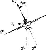
We maintain the acceleration feedback channel in the pitch plane. However, this body-fixed plane is now rotated about the velocity vector through the bank angle <Pbv wrt the vertical plane (see Fig. 9.16). The lateral acceleration is, given the normal load a^,
aL=aNsin<pBV (9.49)
|
Fig. 9.16 Banking aircraft. |
To maintain the same maneuver direction under negative angle of attack, the aircraft must bank in the opposite direction. We see that we must build into the banking logic a switching function that is dependent on the normal load factor sign. Figure 9.17 exhibits the autopilot embedded in a bank-to-tum vehicle. The pitch acceleration feedback autopilot is carried over unaltered from Fig. 9.15. The lateral acceleration command, beyond a small threshold, is divided by the normal load factor, given the correct sign, and limited in magnitude. Now we represent the roll degree of freedom by a simple first-order transfer function (remember our pseudo – five-DoF approach). You should get the value of its time constant Тф from a six-DoF simulation, possibly making it a function of dynamic pressure. Most likely, the six – DoF simulation has a closed-loop roll transfer function of second order. If it is optimally damped (f = 0.7), then the time constant of the first-order approximation is
1
ф 0.707co„
where con is the natural frequency. This converts for a roll autopilot with position and rate feedback to
Тф qSl Kp{Ch-[l/(2Vmp} (9’50)
with Ip the roll moment of inertia, Kp the inner roll rate gain, C;s and С/ the roll control and damping derivatives, respectively. The details are not as important as the facts that the roll time constant increases with moment of inertia and decreases with dynamic pressure.
|
|
Finally, to establish the lateral acceleration aL, the achieved bank angle is multiplied by aN.
For the bank-to-tum autopilot the acceleration command a;v must be given in the normal load factor plane of the aircraft. More frequently, the guidance command will be expressed in the vertical plane. This poses no problem for the skid-to-tum vehicle. However, for bank-to-tum implementations we have to convert it first by dividing it by the bank angle cos фву.
I have to confess to a simplification that I have glossed over so far. The roll DoF in a six-DoF simulation is with respect to the body 1 axis. On the other hand, the bank angle in a five-DoF simulation is about the velocity vector. The two axes differ by the angle of attack. Strictly speaking, the first-order lag in Fig. 9.17 is the representation of the roll loop response, but we interpret it as the bank angle DoF. The effect is negligible, particularly because the angle of attack of bank-to-tum vehicles is usually less than 10 deg.
You can find the details of the implementation of Fig. 9.17 in the cruise missile simulation CAD AC CRUISE5. The gain Gcp could have the value one but is usually increased to two or three to counteract the flattening of the sin <pc curve. To prevent division by zero, I added the small bias of 0.001 to the denominator. The threshold prevents roll oscillations under noisy lateral acceleration commands. A typical value of the threshold is 0.0174 g.
This bank-to-turn autopilot applies to aircraft, cmise missiles, hypersonic planar configured vehicles, and ramjet-powered missiles. If the vehicle cmises for any length of time, it may have to maintain altitude. We now modify the pitch channel to introduce altitude feedback.


