AIM5 Air Intercept Missile
 |
G1 _ G2


 £ si
£ si
I Cl
сл C2 1 A2 I A1 « A3 D1 D2
Fig. 9.39 CADAC pseudo-flve-DoF air-to-air simulation: AIM5.
represents an air intercept missile with a solid, single-bum rocket motor, an acceleration hold autopilot, simple proportional navigation, and a kinematic seeker.
Figure 9.39 depicts the modules of the AIM5 simulation. Each module in CADAC is identified by a two-character code, which is its subroutine name. For clarification a title is added. After the initialization the integration loop starts with the Target Module G1 and ends with the Kinematic Module D2. The integration loop continues until the missile has reached the closest point to the target. Then the Impact Subroutine G4 is executed to stop the mn and to display miss distance information. The sequence of execution is: Gl, G2, SI, Cl, C2, A2, Al, A3, Dl, D2, and finally G4.1 will describe these modules in the same order.
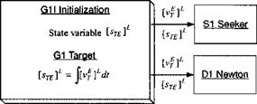 |
The Target Module Gl of an air-to-air missile can be very complex owing to the fact that airborne targets are highly maneuverable and take evasive actions. The SRAAM5 simulation has all of the details, but here we keep the model simple and limit ourselves to targets that fly straight at constant speed. The Target Module, see Fig. 9.40, consists of two subroutines: the initialization subroutine, which prepares the state variable |>г£]і for integration, and the actual target subroutine, which calculates the position of the target by integrating the velocity [vj ]L. Both vectors are sent to the SI seeker and Dl Newton Modules for further processing. Because we assume constant target velocity, the three components of the vector [vf ]L are provided just as input.
The Environmental Module G2 calculates the air density, pressure, temperature, and speed of sound. We make use of the ISO 1962 atmosphere (see Sec. 8.2.1). Accordingly, the temperature and pressure calculations are separated into two altitude layers: troposphere (< 11 km) and tropopause through stratosphere (11 —>• 80 km). The density calculations, based on the perfect gas law, are the same in both layers.
Figure 9.41 provides the atmospheric equations in SI units. In addition, the Mach number and dynamic pressure calculations are given. These parameters are used in the АЗ, C2, and A1 Modules. For backpressure calculations the atmospheric pressure is also needed in the A2 propulsion module. We encounter some problems with the input variable velocity V and altitude H. Following the calling sequence, they are established in D1 after the computations in G2. However, this is not too serious because the time lag is only the length of the integration interval. For the first time computation the initial values of V and H come from the input file.
The Seeker Module SI was discussed in the preceding section. We use the simple kinematic seeker as depicted in Fig. 9.30. In our case we do not model the INS module, i. e., we assume perfect knowledge of the transformation matrix [TBL, which is calculated in the D2 kinematics module.
The Guidance Module Cl has also been detailed earlier in Fig. 9.23, and again the INS is assumed perfect.
The Autopilot Module C2 fashions the acceleration feedback autopilot (Sec. 9.2.3.1) with integral and proportional feedforward. Six state variables are initialized in C2I. They correspond to the Laplace transform variable s in Fig. 9.42: the integrator of the PI compensator and the first-order transfer functions of the rate loop and incidence angle lag dynamics.
The acceleration commands come from the guidance module and are expressed in normal acceleration (positive up) and lateral acceleration (positive right). In an actual autopilot the feedback signals come from accelerometers, either body mounted or as part of the INS. For our simple simulation we use the idealized acceleration, calculated in the A3 Forces Module.
The output of our Autopilot Module is in terms of incidence angles. As you may recall from our discussion in Sec. 9.1.1, pseudo-five-DoF simulations use autopilot transfer functions to model the attitude dynamics. The incidence angles are the output, ready to be used in the aerodynamic tables of the A1 Aerodynamic Module. However, be aware that in the real world the autopilot output are pitch yaw and roll control commands to the control surfaces, which in turn, through the surface deflections, generate moments and produce incidence angles that generate the aerodynamic forces.
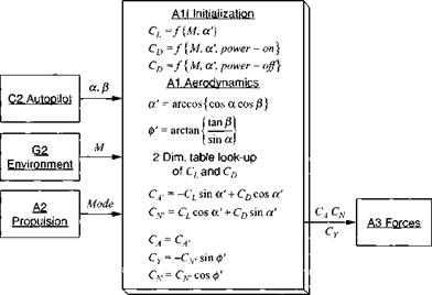
The Aerodynamic Module A1 determines the aerodynamic coefficients from the trimmed aerodynamic tables, provided in the A1 Initializing Module. Because our missile has tetragonal symmetry, we chose the model of Sec. 9.2.1.1. The lift and drag coefficients are a function of Mach number and total angle of attack a’. Drag is also affected by the exhaust plume of the rocket. We must therefore carry two tables power-on and power-off drag.
The two incidence angles, as depicted in Fig. 9.43, arrive from the autopilot and are converted into aeroballistic incidence angles a’ and ф’. With a’, Mach number, and the power flag, the tables are interpolated for Cl and C’D. Before the body coefficients CA, Су, and CV can be sent to the A3 Forces Module, we
![]()
|
have to transform Cl and Co to aeroballistic axes and then through ф’ to body axes.
 |
|||
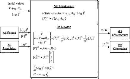
The A3 Forces Module converts the coefficients into aerodynamic forces, combines them with the thrust from the Propulsion Module A2, and sends them to the Module D1 to be used in Newton’s equations (see Fig. 9.44). It also prepares the specific force [/sp]B, the ideal measurement of the accelerometers, to be available for the autopilot. The A3 Modules perform an additional task. The transformation
|
Fig. 9.45 D1 Newton Module. |
matrix [T]BV, derived in Eq. (9.8), is calculated from the incidence angles, provided by the autopilot and is sent to the D1 Newton Module and the D2 Kinematics Module.
The D1 Newton Module is the center of the simulation. Here, the state variables of the vehicle (velocity and displacement) are integrated, starting from the initial conditions. The equations of motion, Eq. (9.27) for flat Earth, are programmed (see Fig. 9.45). They solve for the vehicle speed V and the flight-path angles i^vL, Ovl – At this point the [T]VL transformation matrix Eq. (9.21) is also required for the conversion of the gravity acceleration to velocity coordinates. However, for [T]VL to be available for the first integration, it must be initialized using the initial flight-path angles. After converting the velocity vector to local-level coordinates, the location of the c. m. В of the vehicle wrt an arbitrary Earth reference point E is obtained by integration. Speed V and altitude H are sent to the environmental module and the transformation matrix [T]VL to the Kinematic Module.
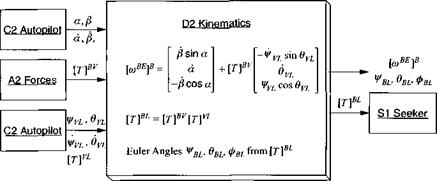
The D2 Kinematic Module, Fig. 9.46, is intrinsic to the pseudo-five-DoF implementation. Instead of integrating Euler’s equations, as in full six-DoF simulations, we derive the body rates [eoBE]B from kinematic relationships, as outlined in Sec. 9.1.5. From Eq. (9.26) we determine the body rates, and Eq. (9.22) provides us with the direction cosine matrix. Figure 9.46 reflects these equations and the extraction of the Euler angles iJ/BL, ввь, Фві from the direction cosine matrix.
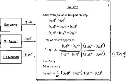
The G4 Stop Subroutine, Fig. 9.47, is not a module as CADAC defines it. It is just a subroutine, called by SUBROUTINE STAGE3, and without the initialization capability of a module. Its purpose is to stop the run and print out intercept time and miss distance.
To get an accurate calculation, a linear interpolation is carried out between the last two integration steps. When the closing speed between the missile and the
|
Fig. 9.46 D2 Kinematic Module. |
target aircraft switches sign, the run is terminated, and the two displacement vectors of the missile sHfj’ and the target sTg ]7 between the last two integrations are calculated. Refer to Fig. 9.47 for the equations, which were derived in Problem 2.9. The integration time step Af and the run time of the next to the last integration step tg are provided by the CAD AC executive routine.
We have circled the whole loop of Fig. 9.39 and defined the major features of each module. I have left off some minor calculations that would have only cluttered the figures. You can find these details in the source code of the AIM5 simulation, stored on the CAD AC CD.
|
|


