Droop reduction or cancellation
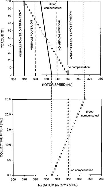
Suppose that for a particular rotor/engine/governor combination it is impossible to satisfy the requirement for adequate stability and respect power-on rotor RPM limits. In this situation a droop reducer must be fitted, the action of which is best described with reference to Fig. 6.8.
The upper chart shows the extent of the problem, before droop reduction is
|
|
|
|
|
|
|
|
|
|
|

employed (see the ‘no compensation line indicated by open circles). If the amount of static droop shown (40 RPM) is required to ensure the governor has adequate stability it can be seen that at both high and low power demands (fuel flow rates) the rotor speed will pass outside the power-on limits. Since the pilot uses the collective lever to make power adjustments it is possible to change the rotor speed datum as the lever is moved. The lower graph shows a typical relationship. The combined effect of the basic
|
static droop law (dependent on spring constant and governor mass) and the rotor speed datum schedule (dependent on the amount of spring pre-load) is shown in the upper chart (see the solid ‘droop compensated’ line). Now the rotor RPM stays within the steady power-on limits at all times. Although it might appear that governor gain has been increased and therefore its stability reduced in fact the governor stability is dependent on the basic droop law and is unaffected.
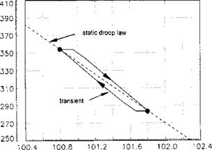
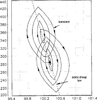
The effect of using droop reduction, or cancellation, on the rotor response can be described relatively easily. Consider the case when the pilot makes a pulse demand or a sizeable gust strikes the rotor. The behaviour of the rotor in this situation is in broad terms a function of the basic droop law and will be little different from the case when no droop reduction was applied. The full effect of droop reduction is seen more clearly when large and rapid power demands are made. When the pilot makes a large collective pitch demand he will cause the datum NF to increase as he raises the lever. Thus the fuel flow to the engine is increased as the power demand is being made rather than as a consequence of the governor sensing a reduction in rotor speed. Therefore droop cancellation will reduce the size of any transients as well as the difference between the stable rotor speed at maximum and minimum torque or collective pitch. The manner in which the transient behaviour of a rotor system is assessed and documented is described later. (Section 6.3.5 and 7.4.6.)


