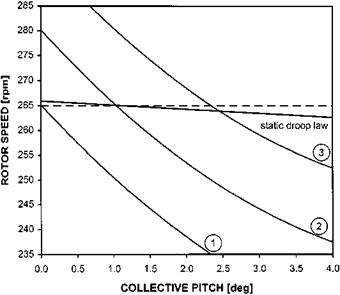
FIG power contribution at autorotative rotor speed
Following a power failure the manufacturer may recommend a suitable value of rotor speed at which the subsequent autorotation should be flown. The value of NR will be chosen such that it is unlikely to exceed limits, the autorotative performance is good and the rotor contains sufficient energy to perform a safe landing. Despite some manufacturers only specifying a range of permitted rotor speeds it will still be necessary to target a particular NR or collective pitch for the purposes of quantifying any power contribution in FIG.
Figure 6.15 shows three possible positions of the autorotative NR versus collective pitch trend relative to the static droop law. In each case a target autorotative NR of 265 RPM has been assumed.
Curve 1. The value of rotor speed generated by an autorotative descent is always below the value demanded by the engine governor. In a power-off descent the pilot will have to lower the collective lever fully to set a NR of 265 RPM. In a FIG at the same collective position the rotor speed demanded by the governor is higher at 267 RPM. Consequently there will be a power contribution in FIG, as the rotor will be driven up to this value by the engine. Alternatively the pilot could raise the collective to around 1° CP and set the target NR of 265 RPM thereby increasing the power
|
Fig. 6.15 Power contributions at autorotative NR. |
contribution. In either case there will be a noticeable difference between the rate of descent power-off and in a FIG.
Curve 2. At a higher AUM or density altitude the NR that can be generated by the ROD is higher and in this situation the governed rotor speed and power-off NR are identical at the CP required to set 265 RPM in autorotation. Thus there will be no power contribution in a FIG and the rate of descent will be the same as in the autorotative case. Since the rotor speed in each case is identical if the pilots sets 265 RPM in a FIG then although the torque will be zero there will be no NF/NR split.
Curve 3. At still higher values of AUM or density altitude the situation becomes clearer. In setting 265 RPM, even with the engines operating at flight idle, the rotor speed can be fully sustained by ROD alone and therefore no power contribution is required. The pilot will need approximately 2.3° CP to set 265 RPM and if the engines were at flight idle he would notice that as well as zero torque being indicated, the free turbine would be governed at approximately 263.5 RPM so a clear NF/NR split would be discernible.
It is perhaps worth reiterating that despite the variations of autorotative NR with AUM and density altitude if during a FIG there is zero torque indicated and a clear Nf/Nr split then there can be no power contribution and the FIG is fully representative of a true autorotation.
6.4 FLIGHT CONTROL SYSTEMS
Early helicopters had fairly simple control systems, consisting of cables and rods connecting the pilot’s controls to the pitch change mechanism at the rotor head. With these early manual systems, the pilot had to apply the necessary force to overcome the aerodynamic loads on the rotor blades, with only some mechanical advantage to aid him. For this reason blade design had to be optimized to maintain nearly constant blade pitching moments over a wide range of collective pitch angles and rotor RPM. These blades were produced in matched sets and were usually of tapered profile and symmetrical blade section. These types of blades presented problems in quantity production and an attempt was made to use metal blades of constant chord which were easier to mass produce, but the control forces were generally unacceptably high. These problems and the growth in AUM led to the widespread adoption of powered controls for helicopters.


