Flight idle glide
6.3.7.1 Flight idle setting and rotor rigging
The speed of the engine/gas generator at flight idle (the minimum speed to which it will fall with the collective lever fully lowered) is a compromise between two requirements. It must be high enough to permit good initial acceleration without risk of surge and low enough to avoid a large power contribution (and therefore rotor overspeeding) when minimum collective pitch is selected. Most governors feature an adjustable minimum flow by-pass to prevent the governor cutting off all the fuel to the engine/ gas generator in the event of a transient overspeed. The by-pass adjuster is used to vary the shape (and hence gain) of the governor’s droop law especially at the low end of the law. This enables the minimum NG in FIG to be increased to achieve stall-free engine acceleration at the expense of increasing the likelihood of a power contribution.
So far in our study of governor characteristics only the upper part of the droop law has been considered. Attention must now be turned to the lower part of the droop law that represents FIG conditions. Although stability within the control system is still important a further factor must also be taken into account: the ease with which the pilot can set a desired rotor speed at low torque. Some droop laws feature a ‘knee’, that provides a lower gain at low torque in an attempt to meet this requirement.
6.3.7.2 Power contribution in flight idle glide
In many rotorcraft it is not practical to retard the throttles when practising autorotations or ‘forced landings’. Therefore, for realistic training flight idle glides should
|
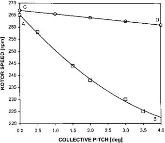
Fig. 6.13 Static droop/autorotation characteristics – FIG power contribution. |
be representative of a true autorotation from the perspective of NR, rotor speed control and ROD. To achieve this the power contribution from the engine(s) must be zero. The characteristics of the rotor system, the engine and the engine control system may prevent this condition from being achieved. For the purposes of this discussion a FIG is a descent with engine condition levers ECL(s) forward and an autorotation is a descent with the ECL(s) retarded or with the engine(s) shut down.
During a stabilized FIG, or powered descent, the engine and a component of the ROD will maintain the rotor speed. On the other hand in an autorotation at a given AUM, airspeed and density altitude there will be a fixed relationship between the collective position and NR. At a constant airspeed in autorotation the rotor speed achieved at a given collective position will the maximum that can be generated by ROD alone, see line AB in Fig. 6.13. At the same conditions in a FIG there will also be a fixed relationship between collective position and NR. This will be the same as the static droop plot for the same flight condition (line CD). In a FIG if the rotor speed demanded by the governing system is greater than the NR that can be generated by the ROD, the engine will, as shown in Fig. 6.13, drive the rotor to the required speed. Consequently there will always be a power contribution in FIG even with the collective lever fully lowered.
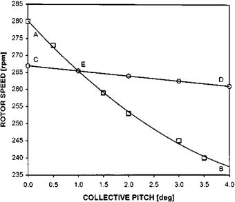
The magnitude of any power contribution in FIG is not fixed as the autorotative relationship will vary with AUM, density altitude, airspeed and rotor rigging. The bypass adjuster and other elements within the engine control system may be used to alter the static droop law. If the relative position of the autorotative NR line and the static droop law are as shown in Fig. 6.14, the response of the rotor to changes of collective pitch in a FIG will be different. At point E the ROD is capable of driving the rotor to the required NR and, therefore, there will be no power contribution from the engine. Note that at point E torque will be zero and NR will be at the value defined
|
Fig. 6.14 Static droop/autorotation characteristics – no power contribution in FIG. |
by the low power end of the static droop law. For the configuration in Fig. 6.14 as the collective pitch is lowered below 1°, rotor speed will follow the line EA whilst NF will follow the line EC. Thus in this flight regime NR and ROD will be the same regardless of the position of the ECL(s) and there will be a discernible NF/NR split. Therefore a FIG descent will have the same flight characteristics as a true autorotation.


