Kinematic seeker
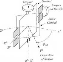
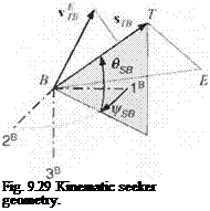
The main purpose of a seeker is to establish (acquire) and to maintain (track) the LOS to the target. We make use of this fact by defining the LOS displacement vector s tb of the center of the target T wrt the c. m. of the body B. With the help of the differential velocity vEB of the center of the target T wrt the vehicle frame B, we can calculate the inertial LOS rate ui0E of the LOS frame О wrt the inertial Earth frame E and send it to the guidance processor. The orientation of the LOS is measured relative to the body by the two angles psth вsb. the seeker azimuth and elevation angles, respectively. Figure 9.29 depicts the geometric situation.
We can derive from purely kinematic considerations the most important variable, i. e., the inertial LOS rates ujoe. We form the LOS vector *tb from the two displacement vectors of the vehicle sBE and the target s TE, where E is an arbitrary reference point on the Earth
![]()
 |
sTB = ste — sBE
then generate the unit LOS vector
S ТВ
НТВ = (9.75)
Is га I
We need also the differential velocity vector vfB, which we obtain from the inertial velocities of the vehicle and the target vf and vE, respectively:
vtb = vt~vb (9.76)
Now, the cross product of the two vectors will provide us with the LOS rate из0Е
Ш°Е = _L Utbvetb (9.77)
Isral
This equation has been derived without reference to a coordinate system and is therefore valid in any coordinate system. We express the LOS rate in body coordinates and the right-hand side in local-level coordinates
W0EB = ~^[T]BLUTB]L[vlB]L (9.78)
lira I
The onboard INS supplies the transformation matrix [T]BL.
For display purposes you can also calculate the seeker angles фзв and в$в from the unit LOS vector expressed in body axes
![]() [utb]B — [T]bl[utb]L
[utb]B — [T]bl[utb]L
from which you get the seeker angles as polar angles
|
(ига)| |
— (итв)в |
|
|
(ига)? |
■y/[(Mra)f] + [(Mra)f] |
|
ifsb = arctan |
|
(9.80) |
Also of interest is the closing speed, which is the relative velocity projected on the LOS
![]() Vc = wFSl[v$b]L
Vc = wFSl[v$b]L
It is negative if the target is closing on the vehicle. The time it takes the vehicle to intercept the target is calculated from the absolute value of the closing speed and the distance to the target. With the assumption of constant relative velocity and nonmaneuvering target, the time-to-go is
![]() _
_
g0_ |VC|
This simple kinematic model serves both radar and EO-type seekers. It represents their ideal performance, unencumbered by field-of-view limits, gimbal dynamics, tracker errors, environmental and target effects. It is useful for simple simulations with emphasis on other than seeker phenomena. I use it to calculate synthetic LOS rates in midcourse based on INS information and to debug guidance simulations before incorporating the actual seeker model. Therefore, you will
 |
find it as a kinematic option in most of the CADAC simulations that incorporate seekers.
Figure 9.30 shows the implementation of the kinematic seeker in the S1 Module of a five-DoF CADAC simulation. The target and dynamics modules provide the kinematic variables to calculate the inertial LOS rates, converted to body axes by the transformation matrix obtained from the INS. Pay particular attention to the absolute velocity V that is sent to the guidance module. When I discussed the PN implementation, 1 distinguished between pure PN with V = | uf | and true PN with V = vjB. The INS can provide the vehicle velocity vf, but not the differential velocity VjB nor can a seeker measure the latter directly. Radar seekers, however, can supply the closing speed Vc of Eq. (9.81).
Although the kinematic sensor model serves mostly ideal seeker representations, it can be adapted to situations that are more realistic. For instance, for acquisition calculations you can use the ideal LOS range-to-gostb I: for field-of-view limits the seeker angles i! jsb and Osb give you the values to establish break-lock conditions; you can add noise to these angles or to the LOS rates to corrupt the true LOS, or you can even apply uncertainties to the target vector Vj to represent target measurement errors.
More realistic sensor models require detailed gimbal dynamics, system noise, target signature, environmental effects, and countermeasures. Most of these error sources depend on the operational frequency band. We will first treat the common dynamic effects and then address radar and FO sensors separately.
9.2.5.2 Dynamic seeker. Tracking of a target necessitates the persistent pointing of the sensor’s beam at the target. The difference between the true LOS and the beam is the tracking error, which is exploited by the tracking mechanism to keep the target in the field of view. Mechanical or electronic gimbals serve this purpose. In the case of mechanical gimbals, the sensor is isolated from the body by a gimbaled platform and is therefore called a gimbciled seeker. On the other hand, if the beam is steered electronically, the antenna is mounted on the vehicle body and is referred to as a strap-down seeker. Radar seekers can be of both types, whereas EO seekers are generally gimbaled. I will concentrate here on the more pervasive gimbaled seekers.
A voltage proportional to the tracking error torques the gimbals of the seeker. This voltage is proportional to the inertial LOS rate. You may remember that the PN law requires just this inertial LOS rate as input. Because the torquers are not
![]()
|
|||
|
|||
|
|||
|
|||
|
|||
|
|||
|
|||
|
|||
|
|||
|
|||
|
|
||
|
|||
|
![]()

![]()
![]()

![]()
®SB’-
The angles foe and в$в are called seeker gimbal angles. You must limit them in your simulation to model the seeker gimbal limits and, for more realism, limit their time derivatives to represent the gimbal rate limits. Typical values for limiting gimbal angle and rate are 63 deg and 400 deg/s, respectively.
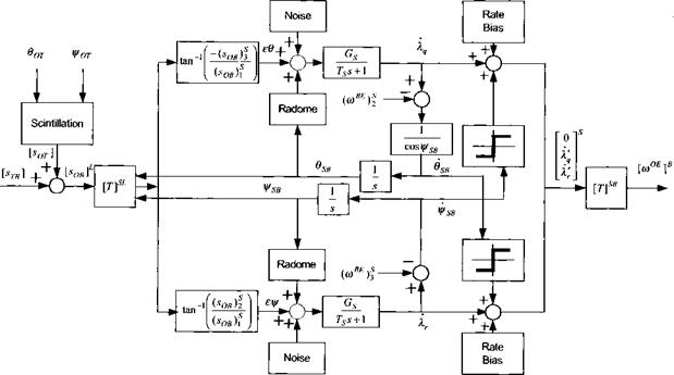
We now build the block diagram that is the basis for our gimbaled seeker model and consider several error sources and dynamic effects. Target scintillation is caused by spatial fluctuations of the reflected energy. If the wavelength is in the radio frequency (RF) spectrum, scatterers that are distributed over the target reflect different amounts of energy as a function of target attitude and aspect angles. For EO sensors energy in the visible or infrared spectrum is emitted or reflected from the target surfaces, giving rise to a similar phenomenon. We model scintillation as a random shift of the aimpoint О from the center of the target T. The stochastic model is a first-order Gaussian-Markov process applied independently to the three coordinates of the aimpoint displacement [sar]T in target axes. The standard deviations could be made a function of the aspect angles вот and – фот of the LOS wrt the target axes. Scintillation shifts the true LOS vectors re to a point at the apparent aimpoint О (see Fig. 9.33). We express the corrupted LOS [s0b in the local-level coordinate system ]L and therefore need to include the transformation matrix [T]TL
[s0BL = [T]tl[sot]T + bra]1
![]()
Wot
![]() [sor ] Istb ] _j_
[sor ] Istb ] _j_
Fig. 9.33 Scintillation.
|
Fig. 9.34 Tracking errors. |
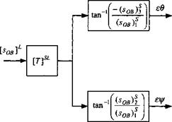
The tracking error is the deviation between the apparent LOS and the centerline of the sensor beam and is measured by the tracker in the inner gimbal coordinates. We transform sobl to the inner gimbal coordinates using Eq. (9.83) and the TM of missile wrt local-level coordinates [T]BL (see Fig. 9.34)
[^b]S = [Гр[Г]в1[^
The pitch and yaw tracking errors єв and єіД are obtained from the components as shown in Fig. 9.34. Because the tracking errors are small angles, we do not expect any trouble from the arc tangent function.
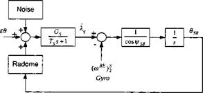
The tracking errors are corrupted by noise and radome errors. Processing of the incoming signal intoduces Gaussian-distributed noise with its standard deviation possibly a function of signal strength. The beam, penetrating the radome, is deflected by the material properties of the radome such that the larger the seeker gimbal angles the greater the deviations. A linear relationship is commonly assumed with a typical value of 1% of the pitch and yaw gimbal angles. Signal processing introduces also a time lag that is modeled by a first-order transfer function with time constant 7s and gain Gs. The output of the tracker torques the gimbals in order to zero the tracking error. This is in effect the inertial LOS rate kq that drives the PN guidance law (see Fig. 9.35).
|
Fig. 9.35 Pitch tracker loop. |
|
Fig. 9.36 Cross coupling and output. |
The torquing signal must be compensated by the vehicle body rates, as measured by rate gyros, mounted on the inner gimbal. For the pitch loop it is the variable (o)B£)f as shown in Fig. 9.35. Furthermore, because the pitch torquer is not located on the inner gimbal but is mounted on the vehicle body, the torquing signal is divided by cos i(rSB. Finally, the integrating effect of the torquing moment produces the pitch gimbal angle 6sb■ A similar loop exists for the yaw channel.
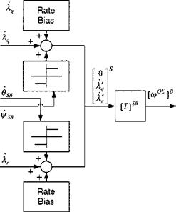
A possible rate bias and coulomb friction cross coupling can further corrupt the inertial LOS rate. The rate bias is caused by friction in the torquers about their respective axes, whereas coulomb friction is dry stiction, a function only of the direction of the angular rate, which couples the two gimbals. Figure 9.36 shows the signal flow of both the pitch and yaw LOS rates. Although the LOS rates are wrt the inertial frame, they are still expressed in inner gimbal coordinates. A final coordinate transformation [T]SB brings them into the form used by the guidance law, i. e., the angular velocity of the LOS frame О with respect to the Earth frame E (inertial frame), expressed in body axes, namely [coOE]B.
To sum up, Figs. 9.33-9.36 are combined and presented in Fig. 9.37. The tracker loops are now closed, feeding back the gimbal angles to form the TM [T]SB, which multiplied by [T]BL yields [T]SI.
Figure 9.37 represents a fairly detailed seeker model, suitable for five – and six-DoF simulations. With the appropriate error values it models missile seekers, both for air-to-air active radar and air-to-ground EO seekers. It can also be used for aircraft acquisition and tracking radar. If the gimbals are reversed, i. e., the outer gimbal rotates about the vehicles vertical axes (outer yaw gimbal), then Eq. (9.83) must be changed, but the block diagram remains essentially intact. The
|
|
only modification is in the tracker loop. The 1 / cos ifrSB term is removed and the 1 / cos 6sb term instead inserted into the yaw channel. One feature that I have left out in the model is the gimbal dynamics. However, they are of such high bandwidth that they have little effect on the LOS rates and can therefore be neglected.
Primary challenges in seeker simulations are the building of the acquisition tables and the generation of error statistics. They will depend on the operational frequency of the sensor. Therefore, we have to discuss the physical implication of microwave and optical systems separately. First, let us treat radar seekers, followed by the EO systems.
9.2.5.3 Radar. The modeling task of radar can be extremely tedious if the signal processing details are the focus. Fortunately, for our simple five-DoF simulations we can adopt a top-level viewpoint and proceed with an error model that corrupts the true LOS. The error sources are target glint, clutter, radome diffraction, and, for gimbaled systems, servo noise, coulomb friction, and rate gyro bias. Electronic countermeasures can degrade both the acquisition and the tracking performance.
The acquisition capability of a given radar sensor is essentially a function of the radar cross section of the target a, the radar scan time Ts (scan duration), and the search area £2 (in steradians). The required level of the signal-to-noise ratio S/N for target detection can vary as a function of ground clutter, atmospheric backscatter- ing, or environmental conditions. For modeling purposes we consider a functional relationship of the acquisition range R, derived from the radar range equation
![]() (9.84)
(9.84)
where К represents the sensor specific constant that contains such terms as average power, aperture, receiver noise temperature, and system losses. To evaluate Eq. (9.84), S/N is expressed in natural units and not in decibels.
The radar cross section of the target, as presented to the seeker, is a function of the target attitude. We can therefore include the target aspect angle in the range calculations, possibly using tables that are functions of azimuth and elevation angles.
A more sophisticated model looks at the individual scattering points that intercept the transmitted electromagnetic energy and reflect portions of it toward the transmitting antenna. The total reflected energy, expressed in radar cross section, is in the form of a Rayleigh distribution (see Sec. 10.3.1.2). From one radar scan to the next, the radar cross section fluctuates according to the random draw from this distribution. This phenomenon is called scintillation. Given an acceptable false alarm rate, the probability of detection becomes a function of the S/N ratio, which is a function of the radar cross section. The greater the S/N ratio is, the higher the probability of detection. Tables relate these three parameters (false alarm rate, S/N, and probability of detection) for a particular radar and target configuration. If you want to bring your model to such a level of sophistication, consult the reference by Hovanessian and Ahn.23
These discussions are equally valid for aircraft and missile radars. In addition, the aircraft radar may have the capability to keep track of several targets while scanning the search area for new opportunities. With this search-while-track
capability the radar computer maintains multiple target tracks that are displayed in the cockpit. The pilot assigns a missile to a target, thus transferring the target state to the missile guidance computer. After launch the missile steers toward the target, possibly receiving (via data link) further target updates. When the missile comes into acquisition range, it turns on its seeker and initiates the search mode. Assuming constant frame time Ts, the acquisition range is according to Eq. (9.84) inversely proportional to the fourth root of the search area. Therefore, the better the midcourse accuracy, the smaller the volume that needs to be searched, and the longer the range at which the target is acquired.
Once target lock has occurred, the seeker must continue tracking the target under adverse conditions like countermeasures, clutter, and atmospheric backscattering. If the noise should increase, the radar may be unable to retain track and may break lock. Hopefully, enough time remains to reacquire the target, or, if the countermeasures emanate from the target, the seeker can switch over to the home – on-jam mode.
A radar sensor measures four quantities: range, range rate, azimuth, and elevation angles of the LOS. These measurements are converted into the displacement Stb of the target relative to the missile and the velocity v j of the target c. m. relative to the missile frame. The angular noise sources, depicted in Fig. 9.35, are of Gaussian nature with the same standard distribution for the pitch and yaw channels:
|
Obw Oq = —— г—- 2VS/N |
(9.85) |
|
where 6bw is the antenna beam width in radians and the S/N ratio is decreasing with range according to the radar range equation.20 Range and range-rate measurements are also random with the following standard deviations |
|
|
C X °R ~ 4ys7N |
(9.86) |
|
Ws R 4VS7N |
(9.87) |
where c is the speed of light, г the pulse length, к the wavelength of the carrier, and Afs the Doppler filter bandwidth. As the missile approaches the target, the signal strength increases and so does the S/N ratio, resulting in improved measurements in all channels. Yet, disturbances like countermeasures, clutter, and backscattering can drive up the noise level, and scintillation becomes more pronounced toward the target.
Clutter is the unwanted energy return from scatterers on the ground, which may enter the seeker through the main or side lobes. Particularly the altitude return through the side lobes can interfere with the target detection process. It is, in general, a difficult undertaking to model clutter accurately. We must be satisfied here with an approximation based on the modified radar range equation. The ground clutter S/N is a function of equivalent clutter radar cross section ac, radar scan time Ts (scan duration), and the search area Q:
Note that ground clutter decreases with the third power of range (as long as the radar beam is smaller than the clutter background.)
Atmospheric backscattering is particularly noticeable in heavy rain. It is a function of the frequency band. The higher the frequency is, the stronger the effect becomes. Again we use the modified radar range equation, introduce the equivalent rain scattering cross section as, and formulate the backscatter S/N
(S/N), = К(9.89)
which decreases with the second power of range and, therefore, not as fast as ground clutter.
Fortunately, Doppler radar can detect targets in clutter and backscattering provided these targets are moving like airplanes and cruise missiles. In effect, the clutter rejection of modem airborne radars is so good that the acquisition range is solely determined by system noise and can therefore be calculated by Eq. (9.84) alone.
For air-to-ground radar against stationary targets, clutter and backscattering are restricting the acquisition range severely. As an example, let the required system (S/N), for target detection be 10 dB. For a given radar against moving targets (no clutter or backscattering corruption), the acquisition range is, let us say, 10 km. If the target is stationary, it can be corrupted by ground clutter (S/N)e = 12 dB and possibly by rain scattering of (S/N), = 20 dB. Under these circumstances, the acquisition range moves closer to the target where the reflected energy from the target is at the higher level of S/N of
S/N = (S/N), + (S/N)c + (S/N), = 42 dB (9.90)
At that range the detectable signal is still 10 dB above the accumulative noise, as required. For our example, the acquisition range has been reduced from 10 to about 1.2 km by the ground clutter and rain scattering.
Once target acquisition has occurred, clutter and backscattering effects are lowered significantly by predictive filtering. Therefore, system noise characterized by Eqs. (9.85-9.87) adequately models the radar tracking noise.
For a pseudo-five-DoF simulation you can start with a kinematic seeker and check out your code thoroughly. If you model an air-to-air missile, you can analyze its kinematic performance adequately and establish launch zones. However, if your interest is in miss distance, you need to upgrade your model to a dynamic seeker and include the major noise sources. For radar seekers you can follow the preceding format and generate the numerical values from the seeker’s specifications. If you design a new missile and the seeker does not exist, you should query the experts— good luck!—and establish several levels of error models. As a result of your analysis, you may be able to define these specifications and thus guide the radar developer in the design process.
Radar sensors, although they exhibit robust performance, may not be accurate enough for missiles with small warheads. Furthermore, their cost can be prohibitive for low-cost solutions. A viable alternative is the EO sensor operating in the visible or infrared spectrum.


