Output devices
Clearly the AFCS needs to move the controls of the helicopter in order to achieve the aims of the control law design, therefore, some form of actuator connected to the controls must be used for this purpose. The actuator may be either electro-mechanical or electro-hydraulic and it may operate in series with, or parallel to, the control run.
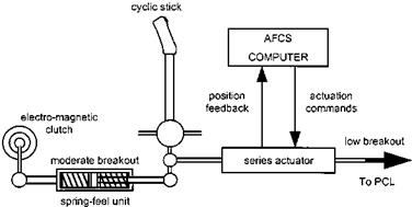
Series actuators can be considered as an extendable portion of the control run whose length is under the control of the AFCS (see Fig. 6.16). Usually the breakout force at the cockpit control is greater than that at the pilot valve of the main control servo and so, as the AFCS actuates the pitch change linkages, no movement of the primary inceptors occurs. In this way the AFCS designer can augment the stability of the host aircraft without causing unwanted movement of the cockpit controls. Transients on engagement/disengagement of the system are possible, as the actuator must re-centre and become a rigid link when the AFCS is inoperative so that no lost motion is introduced. Most control laws involve some enhancement of the damping of the host aircraft by responding to undemanded angular rates. Consequently the series actuators need to be rapid acting and therefore must have limited authority so that the aircraft response to an active failure, such as a hardover or runaway, is not catastrophic and that the available control range following such a failure remains adequate. About +10% is typical, which means that series actuation alone is unlikely to have the control authority to be suitable for all autopilot functions, especially those
|
Fig. 6.16 Series actuation. |
involving large changes in flight path such as automatic transitions and turn coordination.
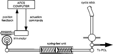
The parallel actuator is coupled to the control run in such a way that the cockpit control is moved as the actuator operates (see Fig. 6.17). Consequently the actuator has full authority and so the actuation rate must be a compromise between the requirement to move the control run rapidly, so that the associated series actuator is prevented from saturating, and the active failure characteristics. Unlike with series actuation there is no AFCS reason for breakout at the cockpit control. The actuator is often coupled to the control run by means of an electro-magnetic clutch and, therefore, disengagement can be made at any time without disturbance to the flight path. It is common practice to provide parallel actuation in the collective and yaw channels because outer loop modes, such as heading steer, often suffer from series actuator saturation. Trim motors acting on the cyclic stick can also serve as parallel actuators in providing a follow-up trim mode that uses the spring-feel unit to move the complete control run, thus keeping the series actuator nulled and able to exert approximately equal authority in both directions at all times. Parallel actuators are usually electro-mechanical as high operating speeds are neither required nor desired.
|
Fig. 6.17 Parallel actuation. |


