Typical AFCS systems for IFR flight
The foregoing discussion has served to detail the qualities of typical attitude-based stability augmentation systems. For IFR flight and the more demanding operational roles the pilot often requires more than pitch and roll attitude stabilization and enhanced yaw damping in the low speed regime. Thus these systems usually provide heading hold/turn co-ordination and possibly height hold. Consequently they will
|
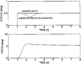
Fig. 6.29 Controls response of an AFCS with trim follow-up. |
|
|
|
|
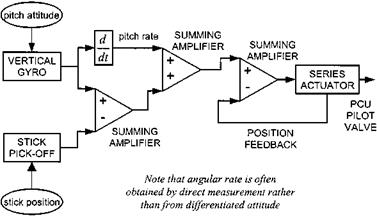
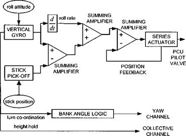
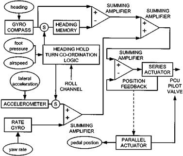
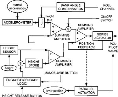
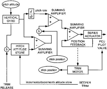
usually consist of a vertical gyro and at least a yaw rate gyro that feed signals to series actuators for stability with a gyro-compass feed for heading hold and an altitude sensor (barometric or radar) for height hold. Although four-axis follow-up trim is becoming increasingly popular, many in-service AFCS have parallel actuation only in the yaw and collective axes with conventional trim provided in the pitch and roll channels. Where autopilot modes, such as automatic transition to/from the hover, are provided the trim motors serve as parallel actuators. Schematics for each channel of a typical AFCS of this class are shown in Figs 6.31 to 6.34.
Differentiated attitude (or true angular rate) can be used to generate rate feedback in the pitch and roll channels but is inappropriate in the yaw channel due to the large voltage change associated with crossing magnetic north. Thus it is usual for AFCS manufacturers to use direct measurement of yaw rate (see Fig. 6.33). Heading hold is usually achieved by comparing the actual heading from the gyro-compass, with the value stored in memory at the instant of engagement of the hold. It is common for
|
Fig. 6.31 Generic AFCS pitch channel. |
|
Fig. 6.32 Generic AFCS roll channel. |
|
Fig. 6.33 Generic AFCS yaw channel. |
|
|
turn co-ordination to be provided, as well as ensuring adequate heading hold up to the lateral velocity limits of the helicopter. Therefore, in addition to featuring parallel actuation to extend the authority of the series actuator, it is usual to find a sensor measuring lateral acceleration or sideslip. Some manufacturers choose to mechanize heading hold directly through a parallel actuator whereas others use the series actuator and follow-up trim.
The response of a rotor to a change in vertical velocity means that the heave axis of a helicopter is inherently stable and therefore it is not always necessary to have series actuation in this axis. A slow-acting parallel actuator is often sufficient to ensure adequate barometric altitude hold. A tighter control of altitude, often associated with a radar altitude hold, will require both series and parallel actuation in the collective channel. Altitude hold is analogous to heading hold in that the actual altitude is compared with a value in memory. Improved altitude keeping can be obtained by using integrated normal acceleration to generate a pseudo altitude rate. This pseudo rate will require bank angle compensation in turning flight since the accelerometer is fixed relative to the body axes whereas the vertical velocity relative to the earth is needed for altitude keeping. Engagement and disengagement of an altitude hold is often less complex than a heading hold system. Typically there will be an altitude hold release switch on the collective lever along with an on/off switch located within the AFCS control head. Some systems feature a ‘manoeuvre button’, also located on the collective, to allow rapid selection of a new altitude datum by the pilot. Whilst this button is depressed the altitude memory is continually updated with the actual measured altitude.
The requirement to provide turn co-ordination complicates the basic stability augmentation system. Heading hold and sideslip control are functions of the yaw channel but it is most natural for the pilot to initiate a turn by means of lateral cyclic stick deflection. It is therefore necessary for the AFCS to incorporate some linkage between the roll and yaw channels so that heading hold can be unlocked when the pilot moves the cyclic laterally or a bank angle above a certain threshold is sensed. Unlocking the heading hold is simply achieved by allowing the heading store to be updated by the current reading from the gyro-compass. In the low speed regime the pilot will need to re-position the helicopter laterally without initiating a turn and thus an airspeed switch is often needed. Simpler systems use foot pressure to make a switch on the yaw pedals as an indicator that the pilot wishes to commence a turn thereby obviating the need for any bank angle logic or airspeed switching. However even sophisticated turn co-ordination logic will require a sensor in the yaw circuit to enable the pilot to perform spot turns.
Although stick cancelling can be engineered to provide a convenient and satisfactory method of informing the AFCS that the pilot wishes to change the aircraft attitude it is not the only possible solution. Some systems (see Fig. 6.35), store the datum attitude in memory and arrange for the pilot to modify this memorized value by various means. For small attitude changes the pilot can use a beeper-trim to increase or decrease the stored attitude as well as changing the stick position. Alternatively, when making large attitude changes the pilot can depress a trim release switch, which in addition to removing the trim forces causes the attitude memory to be updated with the current measurement from the vertical gyro. It should be noted that the application of trim release will also temporarily remove rate stabilization since the open electromagnetic clutch will prevent the series actuator from effecting control. Stick movement
|
Fig. 6.35 Alternatives to stick cancellation – pitch channel. |
without retrimming (against the spring feel loads) is used to open the attitude feedback loop allowing the pilot to manoeuvre around the datum attitude without updating this datum.


