
Our heavyweight helicopter equal in the world does not have
In Rostov started production of the most load-lifting rotary-wing car The Russian holding «Helicopt[...]

Everything about aircrafts and helicopters. News and events in aviation worldwide. Civil, transportation, military helicopters and airplanes.

Everything about aircrafts and helicopters. News and events in aviation worldwide. Civil, transportation, military helicopters and airplanes.

Everything about aircrafts and helicopters. News and events in aviation worldwide. Civil, transportation, military helicopters and airplanes.

Everything about aircrafts and helicopters. News and events in aviation worldwide. Civil, transportation, military helicopters and airplanes.


5.1 An Estimate of the Influence of Endplates
A definite pecularity of the wing-in-ground-effect vehicle compared to the airplane consists of the presence of endplates. Endplates are mounted at the wing’s tips and are intended to decrease leakage of air from under the lifting system. Consequenly, the mounting of endplates results in the augmentation of lift or in a decrease of the induced drag for a given lift. In practice, the configuration of the endplates can vary. Figure 6.1 illustrates schematically some of the possibilities.
According to the approach adopted herein, to account for the influence of the endplates upon the flow past a wing in the ground effect, one has to solve the corresponding local flow problem in the vicinity of the order of 0(h) of the tip of a wing equipped with an endplate. Strictly speaking, the local flow solution includes both homogeneous and nonhomogeneous parts, as is the case for a wing without endplates. However, it can be shown that the ratio of the nonhomogeneous to the homogeneous component is of the order of 0(h). Therefore, to the leading order, the analysis can be restricted to constructing only a homogeneous (circulatory) component of the flow around the wing tip of a given geometry. Such a solution will be reduced to the conformal mapping of the local flow domain onto the interior of the unit strip 0 < S/ae = t/>ae < 1 in the plane of the complex velocity potential /ae = (fae + i^ae-
The solution procedure for the problem will be illustrated for the flow past a rectangular wing with vanishingly thin endplates.


 |
b
K. V. Rozhdestvensky, Aerodynamics of a Lifting System in Extreme Ground Effect © Springer-Verlag Berlin Heidelberg 2000
At first, consider the local flow problem for an edge with a thin lower endplate of height hep. Introduce a complex variable ( = v+y in the physical plane. Map the domain of flow in the £-plane onto the upper half plane ^sg = 92 > 0 by the Christoffel-Schwartz transformation; see e. g. Lavrient’ev and Shabat [129]. The point-to-point correspondence for the conformal mapping is shown in Fig. 6.2. The mapping is obtained in the form
![]() > __ і (t + l)(7ep t) 2(1 7eP)£
> __ і (t + l)(7ep t) 2(1 7eP)£
7Г (l-t)(t + 7eP) 7eP7r(l-t2)’
![]()
![]()
where
The parameter 7ep is related to the height of the endplate through the following equation:
where h* is the local ground clearance, i. e., the distance from the wing’s surface to the ground near the endplate. The mapping of the upper half plane > 0 upon the interior of the unit strip 0 < ^fae < 1 of the plane of the complex potential is performed by the function
g = 9l + i#2 = ехр(тг/ае). (6.3)
For points on the wing,
• on the upper surface,
 |
C = £ + i, 9 = 9l < -P, /ae = ty^ae + i, ty^ae > 0; (6.4)
• on the lower surface,
C = £ + i, 0 >g = gi> – P’, /ae = y? ae + i, </>ae < 0. (6.5)
At the points on the endplate for v — 0,
• on the exterior surface of the endplate,
C = iy, о > у > = – hep, —/3 < gi < —1,
/ae V^ae “b / V^ae ^ (6.6)
• on interior surface of the endplate,
C = іУі = ~hep ^2/^0, —1 < <7i < —(3 ;
![]() /ae — V^ae + І, V^ae ^ 0[28]
/ae — V^ae + І, V^ae ^ 0[28]
To match the local flow solution for the endplate with the asymptotic descriptions of the upper flow and channel flow, we need to know the far – field behavior of the edge flow potential at?/ —> — oo, у = 1 ± 0. These estimates are readily obtained in the following form:
Far from the endplate on the upper surface of the wing (z> —> — oo, у =
1+0),
![]()
V? ae ^ – ln(7ep7TZ>). 7Г
The general form of the solution valid near the wing tip with an endplate has the following asymptotics:
(fe = hai(pae + /га4 + О (/г2). (6.10)
Recalling that the upper flow potential in the immediate vicinity of the wing’s edge has the following asymptotic behavior,
<Aii – ln(h*9) + – A2 + 0(h2), (6.11)
Z7T 7Г
and matching (6.11) with the asymptotic representation of (6.10) far from the edge, one obtains taking into account (6.9),
|
In similar fashion, matching in the region of the flow below the wing, we find ai and the boundary conditions for the channel flow equation (2.22) for a |
Thus, in the problem under consideration, the channel flow potential can be found, as previously, by solving the quasi-harmonic equation (2.22) for the nonlinear case and the Poisson equation (3.14) in the linearized case. However, here, the boundary conditions to be applied at the wing’s planform contour, incorporate the influence of the endplates. Note that in the linear case, the local clearance of the wing near the endplate should be substituted by h.
A relatively simple solution can be derived for a rectangular wing of a small aspect ratio Л; see Rozhdestvensky [44]. In this problem, the upper flow potential outside of the tips is constructed in the same way as for the small-aspect-ratio wing without endplates. The channel flow is determined by using the equation (3.48) with boundary conditions
where h — h/X. The lift coefficient for the lower endplates was obtained in the form
where h — h/X and parameter 7ep is linked to the endplate height hep by equation (6.2). For hep —> 0, the lift coefficient becomes equal to that for the small-aspect-ratio wing without endplates, i. e.,
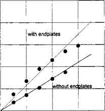
In Fig. 6.3, some calculated results are compared with experimental data for X = 1, h — h — 0.057, hep/h = 0.875.
1.0
![]()
![]()
![]()
![]()
![]()
![]()
 0.0
0.0
The augmentation of the lift coefficient of the wing resulting from the installation of endplates can be characterized by the coefficient
Some calculated curves, showing the behavior of this coefficient versus the relative height hep of the endplate for different clearances h of the wing-inground effect are presented in Fig. 6.4. It can be observed from Fig. 6.4 that the utilization of endplates may result in a considerable increase in the lift. In other terms, for a wing with endplates, the effective aspect ratio may quite noticeably exceed the geometrical aspect ratio.
We turn to the consideration of endplates of a more complex configuration; see Fig. 6.1b. Suppose that the upper part of the endplate has a height hep, whereas the lower part has the height /12. The local flow velocity potential can be obtained by the same technique as for the simpler lower endplate. The lift coefficient for the wing of small aspect ratio with endplates under consideration was found in the form
where parameters 71 >72 > l//?7 are related to the dimensions of the endplate by the following relationships:
 |
Some results illustrating the influence of the lower and upper parts of the endplate upon the lift coefficient of the wing are presented in Fig. 6.5. It is easy to see from the analysis of the graph that the upper parts of the endplates have an insignificant effect upon the increase of the lift. The same conclusion was drawn by Ermolenko et al. [133].
Now, return to a more general problem of the influence of endplates upon the aerodynamics of a wing of arbitrary aspect ratio. As shown above, when the wing tips are equipped with endplates, a change occurs in the boundary conditions, starting from an approximation of the order of 0(h). Consequently, functions ipx and <p2, which characterize, respectively, the first and the second approximations for the channel flow potential, are not dependent upon the parameters of the endplates. On the other hand, the influence of channel flow upon the upper flow is defined by the strength Qi of the source (sink) singularities, distributed along the wing’s planform boundary contour. Due to the fact that
within the approximation considered, the endplates practically do not affect the upper flow.
The previously mentioned considerations lead to the following conclusion: to account for the variation of flow past a wing in the ground effect due to the presence of endplates, it is sufficient to solve the problem just for the corresponding increment of the channel flow potential.
The corresponding boundary problem with respect to this increment (pep for unsteady linearized1 flow around a lifting surface with endplates can be written as follows:
|
9VieP dx2 |
dz2 |
= 0, |
l>x>0, z< A/2; |
(6.26) |
|
V? let |
.(1,2) =0, |
¥>iep |
. . , . flCL і ________________ (x,±A/2) =———— G 7Г |
|
|
7Г dz |
, 2 = ±A/2; |
(6.27) |
||
|
dlPhP dx |
dtfihP dt |
= 0, x = 0, |
(6.28) |
where for thin lower endplates the function G is given by
G(7ep) = + In (1^7ep)3-, (6.29)
1 7ep °7ep
![]()
 |
Nonlinear version can be handled in a similar fashion.
and parameter 7ep is related, as earlier, to the height of the endplate by equation (6.2). Having at our disposal the lowest order flow problem solution, we can readily obtain information on the influence of the endplates for both the steady and unsteady motions of a wing near the ground.
Consider, as an example, the steady motion of a flat rectangular wing with lower thin vertical endplates at given angle of pitch в. The relative increment of the lift due to the endplates is found in the form
к>е p — = 1 + /іС?(7еР)Л(Л) + 0(/i2), (6.30)
Су
where Л is a function of the aspect ratio
 = 4 E”0(-l)ntanh2(gnA2/4)/g3
7гЛ2 E~=otanh<2ntanh(W2)/9n ’
Some calculated results for the coefficient кер versus the aspect ratio Л and for different hep/h are presented in Fig. 6.6. In the limiting cases of large and small aspect ratios of the wing and for hep < 0.5/г, the expression for nep is simplified:
 |
|
• For Л —> 0,
It is not difficult to verify that with an asymptotic error О(h) (where h = h/X) the first of these formulas is compatible with expression (6.18), which was derived from a straightforward solution of the flow problem for a small – aspect-ratio wing.
It follows from the analysis of the formulas presented and Fig. 6.4 and 6.6 that, for a wing near the ground, the efficiency of endplates increases with a decrease in the aspect ratio and/or a decrease in the gap between the lower tip of the endplate and the ground.
In the case considered before, the endplates were assumed to be vanishingly thin. Inclined and/or thick endplates can be handled in a similar fashion. Consider an endplate of a more general polygonal configuration (Fig. 6.7). We map the flow domain around the endplate onto an upper half plane Э > 0 by the Christoffel-Schwartz transformation so that the point As corresponds to аз — —1 (the point-to-point correspondence is shown in Fig. 6.7). The mapping function is
where
F(g) = {g – a2r~g +1)“3-1 • • • (g (6.35)
where a. k = OLk/7Г are the external angles of the polygon.
 |
The Christoffel-Schwartz constants аг, а±,…, dk~ 1 are determined taking into account the point-to-point correspondence in the planes £ and g and depend on the parameters that characterize the geometry of the endplate. The
lift coefficient for a small-aspect-ratio wing-in-ground effect with endplates of polygonal cross section was obtained in the form
|
9X ~ 6/ід ‘ |
(6.36) |
|
|
where |
T f°F(0-F( 0)d, J CL2 £ |
(6.37) |
The endplate configurations presented in Fig. 6.1a, b,c, d can be derived as particular cases from the polygonal shape considered.


