The tail
Helicopters with a single main rotor must have some means of balancing the torque reaction due to driving the rotor. Whilst the anti-torque rotor could be mounted anywhere for hovering, in forward flight the most stable location is aft, supported on some kind of structure called a boom. In addition to the anti-torque function helicopters need some means of yaw control and the tail rotor also serves that purpose. In order to balance the weight of machinery at the tail, the helicopter cabin usually extends some way forward of the mast. This large forward side area is unstable in yaw and generally some fin area is needed to give directional stability in forward flight. A further consideration is that the main rotor on its own is unstable in pitch in forward flight and a tail plane is usually required.
As a result the tail of the conventional helicopter will be a structure supporting a variable pitch tail rotor, its transmission and controls, some fin area and a tail plane. In reality tail booms are also encrusted with antennae, flare launchers, navigation lights, strobe beacons, static vents, registration letters and warning notices, not to mention tail skids and occasionally part of the undercarriage.
In a helicopter with more than one rotor the torque may be cancelled in a different way and a great variety of yaw control mechanisms will be found. These multi-rotor yaw mechanisms are considered in Chapter 9. In this chapter the conventional type of tail rotor will be considered, along with a number of alternatives having various advantages and drawbacks. The conventional tail rotor is well understood and relatively inexpensive owing to its wide use.
The far aft location of the tail rotor assembly means that it must be lightly built in order to avoid the machine becoming tail heavy. The thrust needed from the tail rotor is much smaller than that needed in the main rotor. These two features conspire to ensure that the tail rotor is considerably more fragile than the main rotor. Unfortunately the fragile tail rotor is in a more exposed location where the pilot cannot see it. During certain manoeuvres, such as quick stops and rearward flight it can get very close to the ground, and it may come off worse in any encounter with vegetation the pilot has not seen. Tail rotor blades are usually fitted with soft aluminium ‘telltales’ at the tips which will be distorted by any impact and indicate that a close inspection for damage is required.
Generally the tail boom will be fitted with some kind of skid intended to impact the ground before the tail blades. In some cases this is a tubular structure partially encircling the rotor and known as a D-ring. This gives better protection as well as
being more visible to ground personnel than the spinning rotor. The Enstrom F-28 series has a conspicuous D-ring.
The fast spinning tail rotor is actually very hard to see under many lighting conditions and a significant number of ground personnel have literally walked into one, often with fatal results. The problem is that the human visual system cannot respond to light changes above the critical flicker frequency which is at about 50 Hz. Unfortunately the blade-passing frequency of most tail rotors is beyond this. The result is that when looking at a spinning tail rotor, there is literally nothing to focus on and the eye tends to see only the background beyond the rotor, especially if this is more brightly illuminated than the rotor. A further problem is that when a hovering helicopter yaws, the tail rotor may move laterally at some speed, too fast for someone on the ground to move clear. Unfortunately most helicopters don’t have rear view mirrors and the pilot may be unable to see a person near the tail.
There have been too many tragedies due to these effects, and these can be avoided by some simple rules. Ground personnel should never approach a hovering helicopter or one on the ground with turning blades unless the captain has indicated that it is allowed. If a conventional helicopter must be approached, it should only be from directly ahead, in full view of the captain. Helicopter pilots should avoid initiating rapid yaws in a low hover, as this gives an unnoticed person on the ground no chance of escape and increases the risk of striking the tail rotor on obstacles. It is good practice to paint both dark and bright patches on the tips of the tail rotor blades so that some contrast will be available whatever the background. Painting the patches at a different radius on each blade causes a spiralling or flickering effect that is more noticeable. In the case of a multi-bladed tail rotor, the flicker frequency can be lowered into the visible range by painting all of the blades a dark colour except for one which should be as brightly painted as possible. Another useful safety feature is to have a tail plane-mounted light to illuminate the tail rotor.
An increasingly relevant drawback of the conventional tail rotor is that it seems to generate a lot of noise. Although the tip speed is typically about the same as that of the main rotor, the tail rotor turns at higher RPM and so the blade-passing frequency is higher. This in itself doesn’t make more noise, but human hearing is more sensitive to the increased frequency and so it seems louder. Another problem is that the tail rotor often works in the disturbed wake of the main rotor and impulse noise will be created when a main rotor vortex passes through the tail because this causes rapid variations in local angle of attack.
From some directions the tail rotor may be the noisiest part of the machine. Society is quite reasonably becoming less tolerant of noise, and there is no reason for the aviation community to expect special treatment. In military applications helicopter noise may also be an issue. The helicopter excels at inserting and retrieving special forces, but covert missions are likely to be compromised by excessive noise.
Helicopter designers have explored various ways of countering the main rotor torque in a way that reduces or eliminates one or more of these problems. These techniques give a noise reduction and a safety advantage, but currently at an increased cost. The fenestron system uses a fan enclosed in a short duct in much the same location as a conventional tail rotor. The NOTAR system (NO TAil Rotor) uses a combination of a sideways-lifting tail boom and air jets at the end of the boom. There is a fan inside the hull providing air for boundary layer control over the boom and for the tip jets. These systems will be considered in later sections of this chapter.
The tail rotor needs power and control. The power is generally delivered from the main gearbox by a light shaft supported by regularly spaced bearings to prevent whirling. Flight loads can cause the tail boom to flex and the drive shaft must be
fitted with couplings to accommodate small angular errors and plunging. This avoids putting unnecessary stress on bearings and on the shaft itself. Often the shaft will be run on the outside of the tail boom to allow easy inspection. The shaft may be exposed, or covered by a D-shaped detachable cowling as in, for example, the Bell 206.
The tail rotor gearbox is relatively simple since it has only to turn the drive through 90°. The output shaft bearings will be designed to support the tail rotor and withstand flight loads. An oil level sight glass will be provided, and generally a chip detector. In large machines an oil temperature gauge may be fitted.
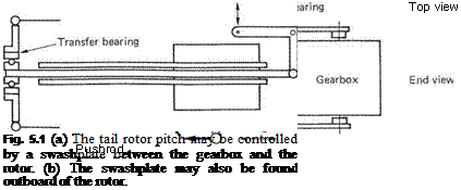 |
The tail rotor only requires collective pitch control and so it will have a swashplate which moves along the shaft axis but without tilting. There are various ways of moving the swashplate via the foot pedals. The pedals usually communicate with the tail using a pair of stranded steel wires, since these are light in weight. Figure 5.1 shows that there is some variety in the mechanisms used to convert the wire motion into movement of the swashplate. Figure 5.1(a) shows an example where the swashplate runs on the gearbox casing between the rotor and the gearbox. A simple bell crank and fork arrangement will move the swashplate. Figure 5.1(b) shows a system in which a pitch control rod runs through the hollow tail rotor shaft to a swashplate which is outboard of the rotor. This may be operated by a bell crank as before. The pitch control rod may be terminated in a coarse screw thread. The wires from the foot pedals are wound round a drum that
rotates the rod in the screw thread. Alternatively the drum may be replaced with a sprocket engaging a length of roller chain inserted in the wire.
An elegant improvement is to couple the collective pitch setting into the tail rotor pitch controls so that to some extent torque variations are automatically compensated. The Westland Lynx has such a system.
In larger machines a power assistance system may be necessary and this will be considered in Chapter 7.
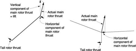
The torque reaction of the main rotor is a pure couple, which is to say it has only a turning effect, and no resultant force in any direction. The tail rotor is mounted pointing sideways at the tail, and so the thrust it produces results in a moment about the centre of gravity of the machine. Unfortunately a moment cannot cancel a couple. The thrust of the tail rotor can be adjusted completely to cancel the rotation of the machine, but if the main rotor thrust is vertical, the tail rotor thrust will cause the machine to move sideways, a phenomenon called tail rotor drift. Tail rotor drift is prevented in the hover by tilting the main rotor disc in the opposite direction. Figure 5.2(a) shows that the main rotor thrust can be resolved into a vertical component opposing the weight of the machine, and a horizontal component. When the latter is equal to the tail rotor thrust, a perfect couple has been produced that opposes the main rotor torque reaction completely. The pitch of the tail rotor blades is controlled using the foot pedals. By disturbing the balance of the couples, yaw control is obtained.
A very slight increase in rotor thrust is necessary so that the vertical component still balances the weight. The tilted attitude of the disc during hover can readily be seen. The hull may or may not tilt due to the disc tilt, depending on the design of the rotor head, the way the transmission is installed and the location of the tail rotor. If the hull tilts, the CM of the helicopter, being some way below the rotor hub, will develop a rolling couple that can only be zero when the CM is directly below the rotor head. The final attitude of the hull will be at whatever angle this restoring couple balances the tilting couples from the rotor head and the tail rotor.
Figure 5.2(b) shows that if the tail rotor thrust is not in the plane of the main rotor, there will be a couple about an axis through the rotor head running in a fore-and-aft direction. The figure shows the situation viewed from the rear of a helicopter having a clockwise-from-the-top rotor and the tail rotor below the plane of the disc. In this case, the side force from the main rotor is above the side force from the tail rotor and this causes a clockwise roll couple called tail rotor roll.
If the tail rotor is above the plane of the rotor (seldom seen in practice), the side force results in an anticlockwise couple. Clearly it is only when the tail rotor shaft is in the plane of the main rotor hub that this couple will be zero, and helicopters which mount the tail rotor high on the top of the fin can achieve this elegant result, although there are more important reasons for such a location, which will be explored in section 5.5.
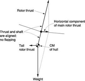
The reader is cautioned that some texts assert that the tail rotor must be mounted at the same height as the centre of mass to eliminate tail rotor roll, but this is incorrect. In fact if the tail rotor is mounted at the vertical centre of mass of the hull, the couple due to the different heights of the main and tail rotor side thrusts makes the hull tilt until it is balanced by the couple due to the laterally displaced CM. This is shown in Figure 5.2(c). The result is that the shaft axis and the tip path axis align and so there is no lateral flapping and the type of rotor head is irrelevant because, with no flapping,
|
(a) (b) |
|
(c) of hull Fig. 5.2 (a) The force from the tail rotor cannot cancel a couple. In practice the main rotor is tilted so that a horizontal component of the main rotor thrust exists. When this is exactly equal to the tail rotor thrust a pure couple has been created. If this is equal to the torque reaction due to driving the main rotor the helicopter will not yaw. (b) If the tail rotor is not at the same height as the rotor head there will be a rolling couple. (c) If the tail rotor is aligned with the vertical location of the helicopter’s CM, the tail rotor roll couple is exactly balanced by the horizontally offset CM so that the main rotor does not tilt with respect to the hull. With all other configurations the hull and the main rotor will have different attitudes. |
there can be no rolling couple from the head. In all other cases the shaft and tip path axes are different and so the type of rotor head becomes significant.
As was seen in Chapter 4, the zero-offset rotor head is effectively a universal joint that allows the hull to hang straight down. Other rotor heads are stiffer and the hull will hang at whatever angle causes all of the couples to cancel one another.
If the helicopter has a zero-offset rotor, and the tail rotor is in the plane of the rotor hub, the fuselage will hang so that the CM is vertically below the rotor head. This will result in a laterally level cabin, assuming there is no payload asymmetry.
In the case of a rotor having offset hinges, a teetering spring or a hingeless head, the rotor head can apply a couple to the fuselage trying to roll the shaft axis in line with the tip path axis. The angle at which the fuselage settles in the hover will now be a function of the rotor head flapping stiffness, the vertical position of the hull CM and the tail rotor roll.
Finally, the designer may mount the main transmission at a suitably slight angle so that the hull stays more or less level with the disc and shaft tilted by the same amount. This means there will be little or no flapping in the hover. The Sikorsky Skycrane is an example of this approach. In the Mi-24 Crocodile (NATO code name Hind), the hull and transmission are tilted with respect to the undercarriage so that disc is tilted at approximately the correct angle. To compensate, the hull is twisted ahead of the main rotor so the cockpit remains level.
In forward flight the hull is moving through the air and so can develop a side thrust if it is set to a suitable angle of attack. If the machine is flown with no sideslip, the side thrust must come from the rotor tilt, whereas if the rotor disc is level, the side thrust must come from side slipping the hull. Clearly the machine can be flown with any combination of these two effects.
The least drag will be suffered if the hull is aligned with the direction of travel, and this may be significant under marginal power conditions. Zero-slip trim has the further advantage that the compass or direction indicator is actually displaying the helicopter’s heading, making navigation easier. Flying at zero slip is aided by an airflow-sensing device showing the direction from which the air is approaching the hull.
Unfortunately most helicopters are fitted with an instrument inherited from fixed – wing aviation, where it is more useful. It is called a slip indicator because in fixed-wing aircraft that is what it does. It is not commonly appreciated that in helicopters the same instrument does not indicate true slip. This will be discussed in detail in Chapter 7.
The conventional tail rotor is mechanically a small main rotor. The term small being relative because, for example, the tail rotor of the Mi-26 is about the same size as the main rotor of an MD-500 and produces a similar thrust. The tail rotor needs no cyclic pitch control, only a collective mechanism actuated by the pedals. Aerodynamically it is also a scaled down main rotor, having much the same physics in the hover, and suffering the same indignity of being thrust through the air edge-on in translational flight.
As the tail rotor is expected to produce thrust in either direction, the blade section will generally be symmetrical and blade twist is only occasionally used. Blade taper can still be usefully employed to make the inflow more even, and this has been seen in practice, although it is not common because constant chord blades are cheaper to make from metal. When blades were made of wood, taper was relatively easy to adopt and as the use of moulded composites grows there is a possibility that taper will make a return.
The teetering rotor has many advantages for use at the tail, and the disadvantages it has as a main rotor are not relevant. As a teetering tail rotor is supercritical (see section 4.15) it cannot suffer from ground or air resonance. The two-bladed teetering tail rotor is simple and therefore light and has become extremely common. Teetering can still be used with four-blade rotors. Two independently teetering rotors can be fitted to a common shaft with a small offset between the disc planes. It is not necessary to mount the two rotors 90° apart; in fact it is advantageous not to do so. Mounting the blades in an X or scissors configuration produces less noise because there is no
longer a dominant blade-passing frequency. Additionally with a carefully chosen skew angle and spacing between the two rotors a small gain in aerodynamic efficiency can be obtained because the axially spaced pairs of blades act to some extent like staggered biplane wings.
As with the main rotor, airspeed alternately adds to and subtracts from the blade speed due to rotation. The resulting roll couple is subject to precession and the result will be flapback and dragging. As the tail rotor tip path axis is tilted backwards due to the flapping, the thrust has a rearward component acting as a drag which the main rotor has to overcome. However, the inflow has a small component along the tip path axis in forward flight reducing the angle of attack and the shaft power needed. The power saved is then available to the main rotor and is precisely the correct amount the main rotor needs to overcome the drag. As a result tail rotor flapping is not detrimental to efficiency but it could lead to stress and/or wear.
In very large helicopters the tail rotor will need both flapping and dragging articulation to contain the stresses and the dragging axis will need damping. In smaller machines it is enough to have flapping hinges. The hinge will often incorporate some delta-three effect (see section 4.7). The delta-three hinge has the effect that as the rotor flaps, some cyclic pitch change is applied. The rotor finds equilibrium with a smaller amount of flapping.
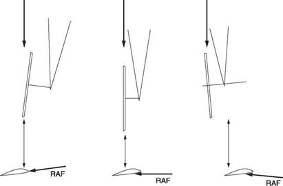
The tail rotor counters the torque of the main rotor in the hover, but it also aids the directional stability of the machine in forward flight by acting as a fin. Figure 5.3 shows how this happens. If the tail swings to one side or the other, a component of the airspeed will change the inflow and with it the angle of attack. The result will be a change of thrust in such a sense as to return the tail to its original position. This is a highly desirable characteristic, except in rearward flight where the effect makes the machine unstable in yaw. An attempt to fly backwards at speed results in the tail swinging round, a phenomenon known as weathercocking.
|
Fig. 5.3 The tail rotor acts like a fin in forward flight because if the machine yaws, the angle of attack of the tail rotor blades will change in the sense that opposes the yaw. |
The tail rotor designer is faced with permanent compromise. Chapter 3 showed that the least power is needed if a rotor has a large diameter and a low, uniform, induced velocity. Profile power is reduced if the tip speed is low. Unfortunately the solidity will have to go up and the resulting tail rotor will be very heavy. To make matters worse, the large tail rotor will have to be mounted further aft to maintain clearance with the main rotor and this will require a longer and heavier tail boom. Ground clearance may also be an issue. There are further problems with large, slow, tail rotors. With a very low tip speed the translational speed will be limited by the growth of the reverse flow area. In the hover if the induced velocity is too low the tail rotor can enter a vortex ring condition during a yaw.
In fact minimizing tail rotor power is not the goal. A more useful goal is to minimize the ratio of the total power absorbed by both rotors to the overall machinery weight. A highly efficient but heavy tail rotor may need more total power as the main rotor has to work harder to lift it. As a result the designer will settle for a tail rotor diameter that contains the weight and clearance problems, and a tip speed similar to that of the main rotor so that the same advance ratio is obtained. As a result the only room for variation is in the solidity and taper. As a design evolves, the solidity can be adapted by changing the number of blades. For example, the Super Puma has four tail blades, whereas the original Puma had five. In some helicopters the high tip speed tail rotor was replaced in a later model with a slower version to reduce noise. This may need more blades to increase the solidity.
The tail rotor and the main rotor are both actuator discs and both produce thrust by virtue of the induced velocity they impart to their respective inflows. The main and tail rotors cannot be considered independently because of their proximity. They can and do affect each other by interaction of inflow to a degree that varies considerably from one regime of flight to another.
In the hover a low mounted tail rotor will actually draw air in from the edge of the main rotor. This will result in an increase in the induced velocity experienced by the main rotor and it will need more power. This might amount to 10-20 kW in a mediumsized helicopter. If the tail rotor is mounted higher the effect is largely eliminated and some power can be saved.
Figure 5.4(a) shows that the increased pressure below the main rotor disc and the reduced pressure above causes air to flow in a toroidal path around the edge of the disc. This is the mechanism of tip loss. The tail rotor operates in this region and there is a strong interaction. When the tail rotor turns in the same direction as the main rotor vortices (b) the relative airspeed of the tail blades is reduced and the available thrust is limited. When the tail rotor turns against the main rotor vortex (c) the performance is considerably enhanced because of the square-law connection between thrust and speed. There appears to be no detrimental aerodynamic effect of this direction, and so it is now considered to be the only direction to employ.
This phenomenon was understood relatively late in the history of the helicopter with the result that many machines were designed with the tail rotor going the ‘wrong’ way. In many cases in later models the tail rotor direction was reversed to universal acclaim. Oddly enough many model helicopters are still designed (if that is the word) with the wrong tail rotor direction. The author has modified a number of models to have the ‘right’ rotation and can vouch for the improvement in these cases also.
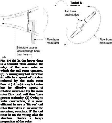 |
As was seen in Chapter 3, with axial flow in the hover the wake of the tail rotor contracts and speeds up just as it does in the main rotor. This means that there is a right way and a wrong way to mount the tail rotor with respect to its supporting structure, which inevitably causes some blockage. The supporting structure may be a slim tube or a substantial tail fin. Figure 5.4(d) shows that if the tail rotor slipstream is directed away from the fin, a so-called ‘blower’, the proportion of the inflow which is blocked is reduced. The relative airspeed at the blockage is also lower. If instead the thrust is directed away from the fin, this blocks a larger proportion of the now
 |
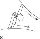 |
Fig. 5.5 A right-side wrong-direction tail rotor (a) can be made into a wrong-side right-direction tail rotor by turning the gearbox over (b). The improvement due to the right direction exceeds the loss due to being on the wrong side.
contracted slipstream which also has a higher relative airspeed. The thrust loss due to blockage will be significantly higher. There is thus a ‘right’ side and a ‘wrong’ side to mount a tail rotor; the blower installation will always be more efficient in the hover. In an ab-initio design, the right side, right direction tail rotor is an automatic choice.
The existence of the right side was appreciated well before that of the right direction, and many machines appeared with this configuration as shown in Figure 5.5(a). When it was realized that the tail rotor should be reversed, cost considerations often dictated the simple expedient of turning the tail rotor gearbox through 180° about its input shaft. This had the desired effect on the rotation, but then put the tail rotor on the ‘wrong’ side as shown in Figure 5.5(b). The improvement obtained by turning the right way exceeds the loss experienced by the increased blockage. As a result there are quite a few right-direction wrong-side machines. The Westland Lynx and the Mil Mi-24 are both in this category. In the Enstrom F-28A, the tail rotor originally went the ‘wrong’ way, but by turning over the gearbox as described the blockage increase was negligible because the tail rotor is mounted on a slim tube. The result was a significant improvement in tail rotor authority.
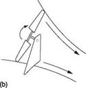
Figure 3.24(b) showed that in forward flight the main rotor produces a trailing vortex structure not unlike that of a wing. The streamlines converge above the plane of the rotor and diverge below it. The tail rotor operates in this airflow and the yaw-stabilizing action is affected by it. When the tail is mounted high, as in Figure 5.6(a) the amount of inflow change for a given yaw is increased by the converging flow, increasing the yaw-stabilizing action. However, a low mounted tail rotor may be operating in the diverging flow (b) where the yaw-stabilizing action is actually reduced.
There are thus many good reasons to mount the tail rotor high on a cranked boom. In addition to power saving in the hover, a high tail rotor is less likely to strike the ground in a low level quick stop, and it enables a safe landing to be made in scrub. The blades are less likely to suffer leading edge erosion from grit blown up by the downwash during hovering. In forward flight a raised tail rotor will produce greater directional stability, and encounters a cleaner airflow. The elimination of tail rotor roll as shown in section 5.2 is an elegant but not an essential bonus.
Unfortunately to site the tail rotor on a cranked tail boom requires an extra gearbox in the tail rotor shaft, and a stiffer tail boom. This adds expense that is unwelcome in smaller machines. In this case the requirement for a little extra power is not a problem because the turbine engine is usually heavily derated. In larger machines, the power loss becomes significant and in very large machines a correspondingly large tail rotor will be required and the issue of ground clearance also arises. Thus a cranked boom is
 |
 |
a better option on a large machine, good examples being the Mi-26 and the Sikorsky CH-54 Skycrane.
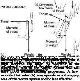
In some helicopters the tail rotor is mounted in an unusual way. The Sikorsky series S-65/Sea Stallion/Sea Dragon is one example. This is a very powerful machine having a high disc loading, three engines and a seven-bladed main rotor needing an equally powerful tail rotor on a cranked boom. Figure 5.7(a) shows that in a conventional installation the side thrust from the high mounted tail rotor puts the tail boom under torsional loading. By tilting over the fin and tail rotor as in (b), the weight of the tail rotor assembly applies a torsional load in the opposite direction and the vertical component of the tail rotor thrust helps to carry the weight of the tail so that stress in the tail boom is reduced. The extra power consumed by the tail rotor is offset by a slight reduction in main rotor power as the latter is no longer carrying the whole weight of the machine.
The Sikorsky Blackhawk also has a canted tail rotor, but for a different reason. In solving various contradictory requirements, this machine turned out with a rearward
centre of mass. The solution was to cant the tail rotor so that it produces some lift as well as side thrust. Canted tail rotors solve some problems but they do introduce interaction between controls. For example, pedal inputs will also cause some pitching. This is usually cancelled out to some extent by interconnections in the control system.
In a still air hover, the slightest imbalance in the two couples will allow a slow yaw. If the pilot applies pedal input, the helicopter will accelerate about the yaw axis, but as it does so the tail rotor will then move through the air at a velocity determined by the yaw rate and the boom length. This velocity will change the inflow conditions and alter the RAF seen by the blades.
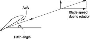
Figure 5.8 shows that the hardest yaw direction is against main rotor torque. The tail rotor has to produce a higher than normal side thrust and the pitch of the blades will increase to provide it. However, as the yaw proceeds, the tail rotor accelerates towards the inflow, so that the inflow velocity increases. This has the effect of reducing the angle of attack of the tail blades. This result is not surprising because in section 4.2 it was seen that the collective control determines the vertical velocity in the main rotor because of the same inflow effect. The yaw rate will come to equilibrium when the change in RAF reduces the angle of attack to the point where the tail rotor thrust imbalance is equal to the drag of the yawing tail boom.
If the yaw is required to be with the main rotor torque, the tail rotor needs to produce less thrust and the blades will be set to a reduced pitch. As the tail accelerates, the inflow velocity falls and this has the effect of increasing the angle of attack, again bringing the yaw rate to a constant value. If a greater yaw rate is required, the blades will need to be set to a negative pitch. This will also be a requirement of yaw control in autorotation where the main rotor torque reaction becomes very much smaller and changes direction.
When in a fast power-on yaw with the direction of main rotor torque, the tail rotor may be in negative pitch and the inflow may reverse. The tail rotor can enter a windmilling state where it is actually being driven by the airflow. At a critical yaw rate the inflow becomes zero. As was seen in section 3.16, zero inflow is an undesirable condition because it causes the rotor to enter a vortex ring or recirculation condition.
|
Velocity of tail due to yaw
Fig. 5.8 When yawing against main rotor torque the tail rotor needs a large pitch angle in order to maintain the angle of attack with the increased inflow velocity. |
This represents a worst case in tail rotor performance. The result of a fast with-torque yaw may be that when the pilot attempts to arrest it there is little response and the required heading may be seriously overshot. This goes down badly in the military as it spoils the weapon aiming.
It should be clear from Figure 5.8 that the tail rotor must have a wide pitch range to allow rapid yaws in either direction and then even more to maintain that degree of control in autorotation. A large positive pitch value is essential to permit a positive angle of attack to be reached despite the high inflow of an against-torque yaw. This means that when the with-torque yaw rate is high the rapid application of full opposite pedal can result in an enormous angle of attack that may be enough to stall the blades.
This is doubly bad, first because the yaw obtained will be in the opposite direction to that intended and second because a stalled tail rotor puts the tail transmission under an enormous torque loading. Everything at the tail of a helicopter is designed to be light in weight and this includes the transmission. Stalling the tail rotor may do damage. Consequently it is considered bad practice to stamp on the tail control pedals. A better result will be obtained if the pedals are operated gradually. In some helicopters tail drives actually did suffer damage and the designers responded by putting viscous dampers on the pedals.
In addition to the yaw function, effective tail power is also needed for sideways flight. It is not obvious why anyone would want to fly sideways, but there are plenty of examples. Large film cameras are often mounted in the main cabin and only have a clear view to the side. Flying the machine sideways allows the camera to shoot forwards. Flying sideways allows the pilot of an attack helicopter to dodge fire whilst keeping his rockets aimed at the target. Pilots who wouldn’t dream of doing the above also fly sideways as a matter of course, because this is exactly what happens when hovering in a side wind. The helicopter only appears to be hovering; it’s actually flying along sideways at the same speed as the wind but in the opposite direction.
In the case of a clockwise-from-the-top helicopter, the wind coming from the starboard side is undesirable as it increases the tail rotor inflow and so requires more power. The worst case will then be where the pilot wishes to make a maximum speed yaw to port in a strong wind from the starboard side. The tail rotor now has to overcome main rotor torque, boom drag due to the side wind and the yaw under conditions of greatest inflow where its angle of attack is reduced. Needless to say this is how the military test tail rotor performance.
Again assuming a clockwise-from-the-top helicopter, there will be a critical airspeed in sideways flight to starboard where the tail rotor is moving at the same speed as its induced velocity and a vortex ring is again a possibility when the pilot tries to arrest the manoeuvre.
Sufficient shaft power is not generally a problem in a turbine helicopter as the main rotor will be in translational lift in a side wind hover and there will be plenty of power available for the tail rotor. The problem is whether the tail rotor can use the power available. The blade pitch cannot be increased indefinitely or the tail rotor may stall. The RPM cannot be increased because of compressibility in forward flight and the diameter can’t be increased because this will need the boom to be lengthened and will reduce ground clearance. One option is to increase the solidity of the tail rotor, typically by adding blades. This is less efficient, but it does at least solve the tail power problem. Other options may include an assessment of the degree of blockage and/or the amount of rear side area.
In a piston engine helicopter the tail rotor may not be powerful enough to allow a crosswind hover above a certain windspeed. In some light helicopters this is not a problem because that windspeed may also exceed the maximum speed at which it is
safe to start the rotors. However, some piston engine helicopters, such as the Enstrom, can safely start the rotors in a gale and on moving to the hover it will be found that the machine simply weathercocks into wind with the pedals only allowing a certain yaw angle either way. The tail rotor is defeated by inflow and cannot obtain an angle of attack.
In any tail rotor operation that increases the inflow, the blade reaction will tilt back and the tail rotor will require more torque to drive it. This torque is provided by the engine, and delivered by the long tail drive shaft. If the tail rotor absorbs more power and nothing else happens, there will be less power for the main rotor. In a simple piston engine machine, where there is seldom any sophisticated engine governing, yawing in the same direction as the rotor turns will result in the machine also tending to descend.
The pilot has to compensate by raising the collective lever slightly, which will then require more engine power. The tail rotor takes roughly 15% of the total power in the still hover and more in the circumstances described above. Many piston-engine helicopters don’t have a lot of surplus power and the pilot soon learns that large pedal inputs in the hover in one direction are to be avoided. Given a choice, the pilot will always prefer to yaw in the direction requiring the least tail power, using smooth and gradual pedal applications. With limited power, yawing must be done slowly as there is no point initiating a yaw in the ‘easy’ direction if it cannot be stopped.
In a turbine-powered helicopter the RRPM is accurately governed and so if a yaw in the direction of main rotor rotation is initiated, the extra torque needed by the tail rotor is automatically provided by action of the governor. As a result the RRpM relative to the helicopter does not change. However, the whole helicopter is now turning with the yaw and so the RRPM relative to the air has slightly increased. One might not expect this to have much effect, but the yaw RPM can raise the effective RRPM by a few percent and as lift is proportional to the square of the RRPM, a significant increase in lift can occur. Thus the turbine helicopter will climb under the same conditions that caused the piston engine helicopter to descend.
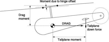
The tail plane is a necessity in forward flight for two reasons. First, because the main rotor alone doesn’t have stability in pitch; and second, because the drag of the hull acts some way below the rotor head, a moment results which tends to pitch the hull down. The nose-down attitude of the hull will result in higher drag than if it is aligned with the RAF. Figure 4.12 showed that an aft-mounted tail plane developing a down force produces a moment in the opposite direction to the hull drag moment.
In a machine with a teetering or zero-offset head there can be no moments from the rotor and so this mechanism determines the hull attitude. The hull will adopt a pitch angle where the drag moment, the tail plane moment and any moment due to an offset CM all sum to zero. The system is stable because if the hull pitches down the (negative) angle of attack increases and produces a restoring moment.
In Figure 5.9 the machine has rotor head offset and the hull drag moment can be balanced by any combination of the tail plane moment and a couple from the main rotor due to the tip path axis being tilted with respect to the shaft axis. In practice a couple from the main rotor will be obtained with the penalty of increased mast stress and some vibration and so it is beneficial to trim the hull attitude in cruise with the tail plane so that a minimal rotor couple exists.
In the hover the tail plane is an unnecessary weight to be lifted and may actually produce significantly more down force than its weight if it is in the rotor downwash.
|
Fig. 5.9 In rotor heads having flapping stiffness, a couple can come from the main rotor to help balance the hull drag. |
This is another example of requirements in hover and translation being at odds. In practice it is not the hover download on the tail plane that is the major problem. Of more concern is the serious fore-and-aft trim change that results should the downwash move clear of or back onto the tail plane. In a teetering or zero-offset machine with limited cyclic power this could cause control problems. In machines having higher cyclic authority, a greater tail plane load in climb and autorotation can be handled. In this case the trim shifts can be handled, but may present an excessive pilot workload, especially if instrument flight is contemplated.
There are three possible solutions to avoiding trim shifts of this kind. One is to ensure that the tail plane is always in the downwash, another to ensure it is never in the downwash and a third is to use a variable incidence tail plane or stabilator. Stabilators are considered in the next section.
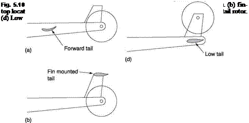
Helicopters often go through a surprising number of tail plane modifications and locations as development proceeds and designers try to find the right combination of characteristics. Figure 5.10 shows some possible locations for the tail plane. At (a) the tail plane is mounted well forward so that it is in the downwash at all but the highest forward speeds. This is the approach used on, for example, the Bell 206 (JetRanger) which has a teetering head. At (b) the tail plane is mounted high on the fin so that it is never in the downwash. This gives the least down force in the hover and a long moment arm for stability at speed, but it does require a stiff and strong fin and tail boom. The MD-500 has a tail plane of this type with the tail rotor below and mounted in-line with the tail boom to simplify the transmission.
Where the tail rotor shaft is mounted in the plane of the main rotor, an out-of – downwash location can be obtained with an asymmetrical tail plane fitted on the opposite side of the fin to the tail rotor. Many Sikorsky machines use this approach, the S-65 being a good example, shown in Figure 5.10(c).
The tail plane can also be put below the tail rotor as in (d). This is almost out of downwash in the hover, but as the machine moves forward from the hover the downwash impinges on the tail plane from above causing a strong trim shift. In this location, however, the tail plane does at least prevent ground personnel approaching the tail rotor.
The section used on the tail plane is subject to some variation. In machines with zero-offset heads, there is no couple from the rotor to prevent hull blowback in forward flight and this must all be balanced by tail plane downthrust. Such machines have limited cyclic control authority and in autorotation the tail plane would produce an undesirable upthrust. One solution is to use an upside-down cambered section that
 |
efficiently produces downthrust in forward flight but which stalls in autorotation. The Bell 206 JetRanger uses this approach.
Another concern is avoiding tail plane stall in the climb where the (negative) angle of attack becomes large. Sometimes leading edge slats will be used. Another solution is to use a device called a Gurney flap. This non-intuitive device consists of a thin tab set across the trailing edge mounted at 90° to the chord line. The effect is to delay stalling up to extremely large positive and negative angles of attack, with a small amount of increased drag at low angles of attack. The Sikorsky S-76B uses such a device.
The stabilator is basically a variable-incidence tail plane that is moved to different angles, generally automatically, according to the flight regime. The stabilator and its actuator will be more costly than a fixed tail plane, so there must be a good reason to employ it. The advantage of the stabilator is that it can be aligned with the downwash so that it can give the stabilizing effect of a tail plane without the unwanted down – or uploads in climb or autorotation. A beneficial reduction in pilot workload will result, along with improved hover performance.
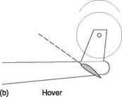
Figure 5.11(a) shows that in forward translational flight the stabilator may assume a slightly negative angle of attack to counter the hull drag moment. In the hover and in slow forward flight the stabilator will move to a large positive angle (b) in order to minimize the download. In a steep climb, the stabilator may also adopt a small positive angle (c). This not only reduces download and aids the climb, but it also levels the hull. In a tandem seat attack helicopter this may give the pilot in the rear seat a better view forward in a climb. Figure 5.11(d) shows that in autorotation the stabilator should move to a negative pitch to avoid an upload which would pitch the machine nose down. In addition to these deterministic movements, the stabilator may also be linked to an artificial stability system based on gyroscopic pitch sensors in the hull.
 |
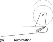 |
Fig. 5.11 The stabilator is a variable incidence tail plane that aligns itself with the direction of airflow in different flight regimes to improve performance. In forward flight, (a) a slight negative angle of incidence produces a downthrust to counter hull drag which acts below the rotor head. At (b) in the hover the stabilator adopts a large positive angle of incidence to prevent the creation of a download. At (c) in the climb a smaller positive angle of attack is beneficial. In autorotation (d) a negative angle of incidence prevents an unwanted upthrust.
Although stabilators are generally considered a good thing, some thought has to be given during the design process to the results of an actuator or control system failure leaving the stabilator in an inappropriate attitude. In a machine with a zero-offset head this would probably not be acceptable. In a machine with higher control power the incorrect tail loads following an actuator failure could be overcome by the cyclic control at least at low airspeed.
In light helicopters the actuator could be a pneumatic device driven by a combination of dynamic pressure from a pitot so that it responds to airspeed and manifold pressure so it responds to power level. It may be advantageous to mount the tail plane on a viscous damper with a suitable time constant that would stabilize brief perturbations whilst aligning to long-term trends.
Fins may be applied to helicopters for the same reason as on fixed-wing aircraft: to enhance yaw stability in forward flight. Secondary purposes of fins may be to allow the machine to fly on following a tail rotor failure or to enhance control in autorotation, especially in helicopters not having a tail rotor.
Fins are seen in a variety of locations as designers seek various compromises. In the case of the high-mounted tail rotor, the tail rotor pylon is naturally extended and streamlined to form the fin. Low-mounted tail rotors with a single fin tend to suffer blockage as the tail rotor and the fin have to be in the same place to clear the main rotor. Blockage can be avoided by using end plates on the tail plane as fins. These also make the tail plane more efficient as tip loss is reduced.
 |
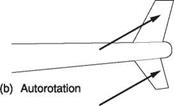 |
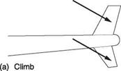
Fig. 5.12 (a) A top-mounted fin is efficient in climb, especially if it has some sweepback. A fin under the tail boom is in turbulent air in the climb. (b) In autorotation the fin under the boom becomes more efficient.
A centrally mounted fin is not in an ideal location as it will be in the turbulent wake of the rotor head and mast. The result may be tail shake as vortices pass the fin. Mounting the fin area at the ends of the tail plane will beneficially move the fins into cleaner airflow.
The helicopter differs from fixed-wing aircraft in that it doesn’t have to move the way it is pointing. A helicopter with a near-level hull may be flying level, climbing or autorotating. Figure 5.12 shows that the relative airflow can approach the fin from a wide range of directions. At (a) in a climb, the RAF is angled downwards, and a top-mounted swept-back fin will present a high aspect ratio and be efficient whereas a bottom-mounted fin is at a disadvantage and may also induce tail shake or ‘squirreling’ because of turbulence around the tail boom.
Figure 5.12(b) shows that in autorotation the position is reversed. The swept top- mounted fin now has a low aspect ratio and will be inefficient. Thus in practice fins are frequently found with upper and lower sections both having sweepback as shown so that good performance can be obtained both in climb and autorotation. The fin of the Bell 206 JetRanger is a good example. The same sweep configuration may be found on end-plate fins such as the BK-117.
A large fin area is beneficial in forward flight and if the tail rotor fails, but it will be a drawback when hovering crosswind as it will create a large source of drag which must be overcome by the tail rotor. As a result fin area must be a compromise. In civilian machines larger fins may be found than those used in military machines because the crosswind hovering requirement is not so important.
Fins are generally, but not always, fixed. In some cases the fin may be cambered and/or fitted at a small angle of attack to offload the tail rotor in cruise. Sometimes the fin may be fitted with a rudder or tab connected either to the pedals or to a yaw – stabilizing system. Pedal operated rudders are more common on coaxial helicopters and synchropters.
Unlike the fins of fixed-wing aircraft, the helicopter fin has to behave predictably over a wide range of possible horizontal RAF directions because of the crosswind hover requirement. One possibility is the adoption of the blunt trailing edge, as if the rear of a conventional airfoil had simply been cut off. This technique allows the fin to operate up to a larger angle of attack without stalling. The penalty in forward flight is remarkably small because the increase in turbulence is balanced by a reduction in wetted area. Blunt trailing edges were adopted on all Chinooks after the CH-47A, and can also be used as a neat way of finishing off the rather fat fin needed to contain a fenestron.
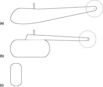
The tail boom must provide structural support for the tail rotor, the fin and the tail plane, as well as having some aerodynamic characteristics. Figure 5.13(a) shows that a tail boom which is a smooth continuation of the hull will have lower drag in forward flight than the ‘pod and boom’ construction shown at (b). However, a wide tail boom will suffer a greater download in the hover. Figure 5.13(c) shows that the tail boom often has a rounded rectangular shape to allow reasonable depth without excessive hover download.
A streamlined tail boom may be practical on an executive transport, but for other purposes rear loading ramps or clamshell doors may be needed and these always result in a hull having higher drag. The boom has to be high set and slim to give clearance for rear loading.
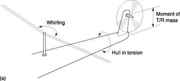
The tail boom effectively couples two masses together; the main rotor and the tail rotor. These will each experience different forces, some static and some alternating. The main rotor will apply vibrations to the hull, but the tail rotor will tend to lag behind because of its mass and the result will be stress on the tail boom. Figure 5.14(a) shows that when starting, whirling forces from the main rotor will rock the hull from side to side. A tail rotor mounted atop the tail fin will resist the rocking and place the tail boom in torsion. The mass of the tail and the torsional stiffness of the boom will create a resonant system and if the resonant frequency coincides with an exciting frequency the tail assembly will oscillate in torsion.
If torsional oscillation results from a flight frequency, the resonant frequency will have to be changed. Intuitively, stiffening the tail boom would do this, but weakening it would also change the resonant frequency to a lower value. A lengthwise slot in the
|
Fig. 5.13 (a) A hull in which the tail boom is smoothly faired into the cabin will cause less drag in forward flight. (b) A pod-and-boom structure suffers from turbulence at the rear of the pod. (c) Tail boom cross-section which is deep but narrow gives strength without excessive download in the hover. |
|
|
|
Fig. 5.14 (a) Main rotor lateral rocking during start-up places the tail boom under a torsional load. The inertia of the tail rotor and gearbox may combine with the torsional stiffness of the boom to produce a resonance. (b) Fore-and-aft rocking causes bending loads in the tail boom with a potential for resonance. |
skin of a tail boom will reduce the torsional oscillation frequency without materially altering the bending stiffness. Damping material may be placed across the slot where it will be highly effective. Figure 5.14(b) shows that main rotor whirling in the fore- and-aft direction subjects the tail boom to bending loads as does tail rotor imbalance. Again a resonance may be present. The Robinson R-22 passes through some quite noticeable tail boom bending resonances during rotor starting and the rotors must not be run continuously at the RPM that excites them.
As the tail boom is in the downwash of the main rotor, it will create aerodynamic forces. Figure 5.15(a) shows that in still air the force will be primarily downwards, possibly with a slight, and beneficial, sidethrust due to swirl. However, if there is a crosswind, the resultant of the crosswind and the downwash will be a non-vertical RAF seen by the boom. This may result in a significant amount of boom lift, shown at (b) which is not necessarily in a useful direction. If the boom lift opposes the tail rotor thrust, this may restrict the crosswind hovering performance. A possible solution is the addition of a boom strake mounted high on the boom. This has the effect of causing early separation and a reduction in the amount of lift developed.
A cylindrical shape may be great for the pressurized hull of an airliner that goes the way it is pointing, but it is generally less than ideal for transverse flow. This is because transverse airflow across a cylindrical shape is unstable. Separation takes place from alternate sides causing lift in alternate directions. Those spiral strakes fitted to factory chimneys are designed to cause flow separation at defined points in order to prevent shaking in a wind. A rounded helicopter hull or boom will also suffer from an indeterminate separation point and this may result in chaotic shaking in the hover. In this case a strake fitted low on the boom will produce a defined separation point and reduce the shaking. Boom strakes generally align reasonably well with airflow in cruise and so have little detrimental effect.
 |
High strake position
![]()


![]()
 Sidethrust opposing tail rotor
Low strake position
(a) Still air hover (b) Crosswind hover
 |
|
Fig. 5.15 (a) In still air hover, downwash on the tail boom is vertical except for a swirl component. (b) In crosswind hover, the resultant airflow direction due to downwash and wind may cause significant boom lift. If this opposes the tail rotor thrust the crosswind hover performance may be impaired. A high-mounted boom strake may be used to suppress boom lift in crosswinds, whereas a low-mounted boom strake may be used to define a separation point for downwash in the hover and thereby reduce shaking.
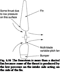
The fenestron is basically a ducted fan built into an opening in the tail fin and was developed by Aerospatiale. The name comes from the French fenetre meaning a window. It is commonly thought that the fenestron works like a small tail rotor, but this is not quite the case. In fact the fin structure is responsible for a significant amount of the system thrust. Figure 5.16 shows that the fan in the fenestron is a multi-bladed variable pitch device of high solidity. However, the fan is set in a duct that is relatively
long. The cross-section of the duct matches the stream tube contraction as the fan is approached and so the reduced pressure caused by the fan is applied to the duct. As a result the effective area of the fenestron is the area of the duct mouth. The close fitting duct effectively prevents blade tip loss. The direction of rotation of the fenestron should be chosen on the same basis as that of a conventional tail rotor, namely the bottom blade going towards the nose.
An advantage of the fenestron is that as it is set in the fin, there can be no fin blockage as happens with a conventional tail rotor. In fact the fin is augmenting the effect of the fan. The fenestron presents a much reduced hazard to ground personnel and is quieter. However, as the fenestron is inseparable from its duct assembly, a powerful fenestron can become quite large and ground clearance may be an issue. Some machines equipped with fenestrons have a sacrificial collapsing bumper intended to absorb the energy of an unintended ground contact after which it must be replaced.
A helicopter without a tail rotor has a number of advantages. It can land in scrub without damage, ground personnel are less likely to be injured and there may be a reduction in noise. The first attempt at a tail rotorless machine was the experimental Weir W-9, shown in Figure 5.17, that flew in the UK in 1944. This machine had a piston engine that, in addition to driving the main rotor, drove a variable pitch fan to blow air
|
Fig. 5.17 The Weir W-9 had no tail rotor but instead ducted cooling air and exhaust gases down the tail boom to provide an anti-torque jet reaction. Twenty-five per cent of engine power was lost in the anti-torque system, which was not pursued. |
down the tail boom, cooling the engine in the process. The exhaust gases were mixed in to provide further energy. At the rear of the hollow boom the gases were ejected from a sideways-facing nozzle at about 150 feet/sec (45 m/sec). The Weir was also unusual in having a constant velocity joint in its zero-offset rotor head. The Weir proved that the tail rotor could be eliminated, but it also proved that a simple fan/nozzle arrangement is very inefficient: around 25% of the engine power was consumed in the anti-torque system.
Stanley Hiller built a similar machine that flew in 1946. At around the same time Antoine Gazda built the Helicospeeder. These had piston engines. In France in 1954, Nord flew a machine called the Norelfe that used the exhaust from its turbine engine to oppose torque. All were abandoned. Today it is clear that these results follow from momentum theory. It is less efficient to derive thrust by ejecting a small cross-section of air at high speed than it is to eject a large cross-section slowly.
These experiments were enough to convince the industry that the tail rotor would not quickly be replaced; not in fact for about 30 years. In the 1980s, McDonnell Douglas developed a viable system which they called NOTAR and which does not require any more power than the conventional tail rotor. The NOTAR system has two components, a unidirectional system that provides about 60% of the anti-torque requirement, and a bi-directional system that provides the remainder of the thrust as well as providing yaw control.
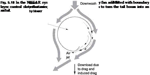 |
The unidirectional system uses the tail boom as a wing operating in the rotor downwash. The tail boom is cylindrical and boundary layer control is used. Figure 5.18 shows that on one side of the boom are two downward facing slots fed with air from the interior and pressurized to about 1 psi by a fan. The air emerging from the slots energizes the boundary layer and delays separation significantly so that the downwash flows around the boom and exits with a sideways component. Effectively the downwash has been accelerated to the side and the reaction to this is a thrust on the boom. The thrust has a lateral component and a downward component corresponding to the induced
drag. However, the slots are emitting downward jets and this causes some upthrust that nearly cancels the induced drag leaving a side thrust to counteract the torque.
About 60% of the anti-torque thrust comes from the boom. The remainder comes from a nozzle at the extreme end of the boom. This has a stationary inner part and an outer rotating sleeve. The inner part has a port on both sides, whereas the outer part has a single port. The pilot’s foot pedals rotate the sleeve so that it will uncover one or other port to allow yaw control. The degree to which the sleeve turns determines the amount of port opening and so controls the thrust.
The boom is pressurized by a variable pitch fan. The pitch required is not a simple function of the pedal position and never becomes negative. Instead it is a function of how much thrust is needed. In other words the application of right or left pedal will cause the fan pitch to increase to provide extra airflow to the yaw control ports. In the case of autorotation the boom will be in upwash and the boundary layer control is no longer effective, but nor is it needed. The fan is driven from the main rotor and yaw control is by rotating the tail sleeve as usual.
The NOTAR system is remarkably quiet and safe and demonstration pilots have made their point by backing the tail boom into bushes and using back cyclic so that the machine rests on the rear of the skids and the end of the boom.
In the absence of a tail rotor to weathercock, the NOTAR machines, not surprisingly, need a substantial amount of fin area. In the production machine, minor yaw instability is handled with a gyroscopically controlled rudder tab on one of the fins. It is possible that this is not a fundamental problem and further development may eliminate it.
It is often overheard that loss of tail rotor drive will cause the machine to go out of control, but this is not necessarily the case. If the tail rotor drive fails without causing other damage and the machine is put promptly into autorotation, the torque reaction of the main rotor will cease, and the tail rotor will be unnecessary. In some machines the tail boom and fin area are large enough to counteract engine torque by yawing into the slipstream at reasonable translational speed and then autorotation will only be necessary for landing. Nevertheless most pilots would rather lose the engine than the tail rotor drive.
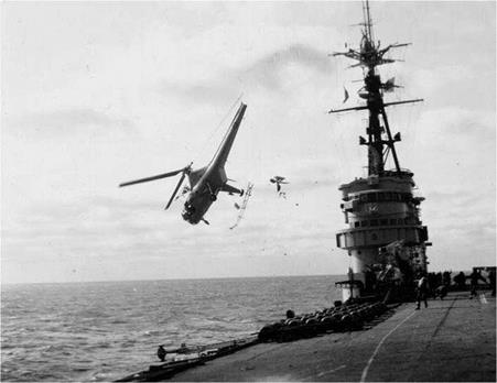
Unfortunately tail rotor failures can result in more than loss of drive. A failed component in the rotor can cause serious imbalance and this can tear the whole tail gearbox out of the boom. A broken drive shaft may flail and destroy hydraulics and wiring or even sever the boom. In these cases the machine will suffer a serious forward CM shift and a loss of rear side area. A machine with a zero-offset rotor head probably wouldn’t retain control. Figure 5.19 shows a zero-offset helicopter that has developed a serious nose down trim having lost its tail rotor in a collision with a ship. A machine with a substantial tail boom and a rotor head having a wide CM tolerance would have a much better chance.
Despite all the theory, retaining control requires the pilot to take the correct actions and in order to take good decisions the pilot has to know the situation. In the case of tail rotor problems the pilot cannot see what is wrong and has to deduce the problem from whatever symptoms of vibration, noise, yaw and pitch he experiences. When this happens suddenly it is asking a lot of the pilot to do exactly the right thing. Nevertheless many pilots have walked away from tail rotor failure, in some cases with no further damage to the machine.
|
Fig. 5.19 Following a collision with a ship, this helicopter has lost its tail rotor and gearbox. Having a zero – offset rotor head, there is insufficient cyclic authority to oppose the serious trim shift and the nose down attitude that results is apparent. |
Others were not so fortunate and consequently regular inspection of all components associated with the tail rotor is to be recommended.
One point sometimes overlooked is that as the tail rotor is at the back, anything that comes off or out of the helicopter in forward flight can strike it. The designer may try to think of every eventuality, which is why the fuel filler cap is often retained by a length of wire, but there have been cases of engine access covers coming loose in flight and inflicting grievous harm to the tail rotor.
Helicopters are often flown with one or more doors open or removed, for film and television shooting, for example. In this case it is essential that everything within the machine is fixed, stowed or tethered. The helicopter with a high set tail rotor is at an advantage here, as debris is more likely to pass below it.
6


