Thrust vector control
Instead of using aerodynamics to turn the vehicle, thrust vector control employs propulsive moments to increase the incidence angle and thus maneuvers the vehicle through the ensuing aerodynamic forces. Outside the atmosphere, in the absence of aerodynamics, direct force control must be applied, using reaction control jets. We limit our discussion here to the endo-atmospheric application of thrust vector control.
A common feature is the deflection of the propulsive vector from the vehicle centerline in order to produce a moment about the vehicle’s c. m. The deflection can be produced by turning the exhaust plume with jet tabs, like the original German V2, by pintel nozzles or titling the whole nozzle assembly. In either case the simulation model is the same. We use the moving nozzle as an example.
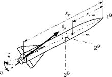
Figure 10.23 explains the geometry. The moment arm is the distance between the throat of the nozzle and the c. m. of the vehicle: Д* = xp — xc m. |. (As a reminder of what you learned in earlier chapters, I have drawn the body axes not
|
|
through the c. rn.). The nozzle deflection is given by yaw angle £ in the 1B, 2B plane and the pitch angle r) in the displaced 1B, 3B plane. With the sequence of transformation of the nozzle coordinates wit the body coordinates ]B,
you should be able to derive the following transformation matrix:
![]() COS £ COS tj sin £ COS 7] —sin£ cos£
COS £ COS tj sin £ COS 7] —sin£ cos£
COS £ sin Г] sin £ sin T]
The thrust force in body axes is
ifP]B = mNBuP]N
where [fp]N = |f 0 0] with t as the thrust magnitude. Substituting the transformation matrix yields
![]() cos ri cos £
cos ri cos £
cos г) sin £ t
—sin Tj
The vector product of force and moment arm produces the moments about the c. m. that turn the missile:
|
0 |
-Up) f |
Up) B2 |
|
|
Up) f |
0 |
-Up)? |
|
|
-Up)! |
Up)? |
0 |
|
|
0 |
|||
|
— sin Г] |
txp |
-^c. m. 1 |
|
|
— COS Г] sin £ |
|
[mp}B = |
 |
Either a positive £ or tj causes a negative moment. Notice also that the force components oppose the maneuver, just as it is the case with aerodynamic controls. For instance, a positive t] produces a force component (fp)B = —t sin??, which counteracts the pitch-down maneuver. This adverse control force is noticeable at the beginning of the maneuver until the aerodynamic force, produced by the incidence angle, overpowers it. To avoid this effect, aerodynamic control surfaces and reaction jets have been placed forward of the c. m. Located there, they actually aid in the maneuver.
A drawback of TVC is the lack of roll control. Twin nozzles and peripheral reaction jets have been applied to overcome this deficiency. However, they come at a cost and performance penalty.
The dynamic response of gimbaled nozzles can be patterned after the model we used for aerodynamic controls Fig. 10.21. With two gimbals we introduce the r and £ actuators into the control loop. Typical values for their deflection and rate limiters are 10 deg and 100 deg/s, respectively. You can find applications of TVC in the CADAC SRAAM6 simulation, Module C3.


