Our heavyweight helicopter equal in the world does not have
In Rostov started production of the most load-lifting rotary-wing car The Russian holding «Helicopt[...]

Everything about aircrafts and helicopters. News and events in aviation worldwide. Civil, transportation, military helicopters and airplanes.

Everything about aircrafts and helicopters. News and events in aviation worldwide. Civil, transportation, military helicopters and airplanes.

Everything about aircrafts and helicopters. News and events in aviation worldwide. Civil, transportation, military helicopters and airplanes.

Everything about aircrafts and helicopters. News and events in aviation worldwide. Civil, transportation, military helicopters and airplanes.


If any blade eement exceeds the drag divergence Mach number for its airfoil, the power required will be higher than that calculated from the closed-form equations. Before developing the method for estimating this power loss, it is appropriate to discuss the three-dimensional phenomenon known as compressibility tip relief.
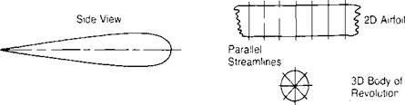
The relief effect is seen clearly by comparing the streamlines on a two – dimensional airfoil and on a three-dimensional body of revolution with the same thickness ratio shown in Figure 3.37. On the two-dimensional airfoil, the streamlines are constrained to remain parallel to each other but on the body of revolution, they spread out as they approach the maximum thickness thus reducing the local velocity and increasing the free-stream Mach number at which drag
divergence occurs. The blade tip may be thought of as a combination of a two* and three-dimensional body and, as such, would be expected to have a drag divergence Mach number that lies between those of the other two bodies. Wind tunnel tests of wings, reported in reference 3.20, verify this expectation by showing that the drag divergence Mach number increases as the aspect ratio is decreased.
Tip rebel consists of two parts: a large one due to the reduction of the effective Mach number, which delavs the formation of the shock wave, and a smaller one due to the reduction in the local dvnamic pressure, which reduces the actual drag and, thus, the drag coefficient based on the free-stream dynamic pressure.
A method for estimating the tip relief for rotor blades is given in reference 3.21 based on the similar analvsis for wings of reference 3.22. With this method, both the reduction of Mach number and that of drag coefficient may be calculated as a function of the blade thickness ratio and the distance from the tip. The method is suitable for detailed computer studies, but for a quick estimate of tip relief, a simpler method is available. The simpler method is based on the fact that the tip of a blade with a thick airfoil will act more like a three-dimensional body and thus will have a greater tip relief than the tip of a blade with a thin airfoil. A convenient velocitv parameter that is a function of the airfoil thickness ratio is the incompressible two-dimensional velocity ratio, (z F), and the average of this ratio along the chord is used to define the effective Mach number at the tip.
![]()
 |
 |
M
The local velocity ratio, г/V, as a function of chord can be calculated using airfoil theory or can be derived from wind tunnel measurements of the pressure
coefficient distribution since:
|
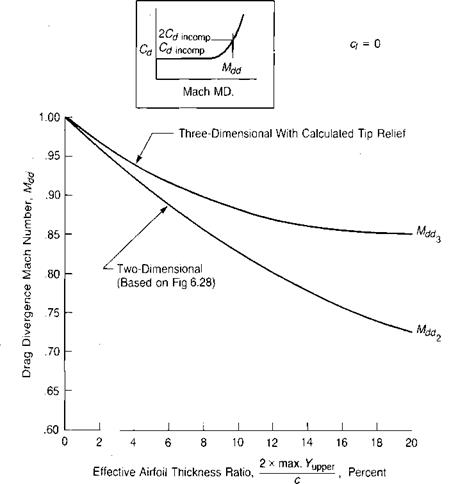
|
For many airfoils, the local value of {v/Vj1 is plotted against chord in Appendix I of reference 3.23. These plots have been used to find the average velocity ratio at zero angle of attack and the corresponding tip relief for several families of airfoils. The correction has been applied to the test data shown in Figure 6.28 of Chapter 6 to produce Figure 3.38, which shows the two – and three – dimensional drag divergence Mach numbers as a function of the effective thickness ratio. The method has been used to correlate with flight test data given in references 3.24 and 3.25. The results shown in the following table demonstrate a satisfying degree of agreement.
|
|
A further check has been made applying the method to the fixed-wing example of reference 3.22. For this case, the wing had a NACA 0012 airfoil and an aspect ratio of 3.25. The method of this section was adapted to the wing by assuming that the tip relief linearly decreased to zero one chord length in from each tip. The average Mach number relief for the wing, therefore, was less than the extreme tip value. Figure 3.39 shows the experimental drag measurements for the
 |
Airfoil — NACA 0012
Source of test data: Anderson, "Aspect Ratio Influence at High Subsonic Speeds,” Jour, of Aero. Sci. 23-9, 1956.
low-aspect-ratio wing and estimates for a wing of infinite aspect ratio using both the sophisticated method of reference 3.22 and the simple method of this section. Again, the degree of correlation is satisfactory at least near the drag rise area, which determines the drag divergence Mach number.
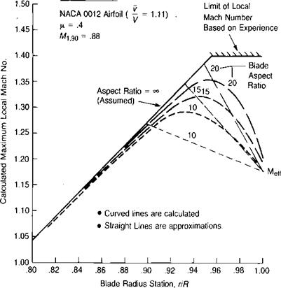
Additional justification of the procedure is developed by comparison with calculations of the spanwise distribution of the maximum local Mach number for blades of aspect ratios of 10,15, and 20, shown in Figure 3.40 taken from reference 3.26. The airfoil is the NACA 0012. The calculated curves are compared with straight lines, which follow the assumptions just discussed. The assumptions appear to be very good for the aspect ratios of 15 and 20, though somewhat extreme for the – aspect ratio of 10.
An approximation to the additional torque due to compressibility may be obtained by integrating the extra drag from the radius station at which the drag first rises above the incompressible value to the tip. In forward flight, the advancing tip normally operates at very low angles of attack so that to a first approximation, the compressibility losses can be related to the airfoil drag characteristics at zero lift. Test results show, however, that the losses are also a function of CT/o. The procedure adopted for this analysis has been to derive the
|
basic equations using the zero-lift drag characteristics of the airfoil and then to establish an empirical correction to the drag rise Mach number as guided by wind tunnel and flight tests of actual rotors producing thrust.
 |
||
The geometric relationships that enter into the analysis are shown in Figure 3.41, where (r/R)dr is the radius station at which drag rise is first experienced and ф, and i|/2 are the azimuth angles bounding the drag rise region. The equations for these two parameters
 |
and Mdr is the Mach number at which drag rise first appears.
The drag increment, Acd, is a function of Mach number. Figure 3.42 shows the drag for a
The value of Mdr is a function of the spanwise position of the blade element, being the two-dimensional value, M*, inboard of one chord length, and being the three-dimensional value, ЛЦ, at the tip. Thus for the inboard section:
-< i–
R R
and for the tip section:
With these relationships, it is possible to evaluate the quantity, (ACQ/<Jcomp)/Mn/, as a function of the airfoil characteristics, Kx and MdrjMdrj the chord to radius ratio, c/R; and the flight conditions, MdrjMm, and jx. As an example, the integration has been carried out assuming the 0012 airfoil with:
(Assume Л1*/ЛЦ = ЛЦ/ЛЦ from Figure 3.38.)
Figure 3.43 shows the results of this integration in terms of the amount the advancing tip Mach number exceeds the three-dimensional drag rise Mach number. Although Figure 3.43 is based on the 0012 airfoil, it should be valid enough as a first approximation to be used with other airfoils suitable for rotors using either two-dimensional wind tunnel results or the value of Л1* from the upper portion of Figure 3.43, which has been generated using figures 3.38 and 3.42 as guides.
The effect of CT/o on compressibility losses has been incorporated into the method after examining the full-sale wind tunnel results of reference 3.27 and the flight test results of reference 3.28. Although there is not complete consistency between the various sets of test data, a reasonable approach appears to be to assume that Л1* has the form:
Ж*, = Md [1 – 6(CT/a)2]
3 3ci=0
Satisfactory correlation of the method with wind tunnel test results is shown in Figure 3.44.
For those more sophisticated rotor analyses using computers with stored tables of two-dimensional lift and drag coefficients as a function of angle of attack
 |
and Mach number, the tip relief may be accounted for by calculating an effective Mach number for the blade elements within one chord length of the tip such that:
Source: McCloud, Biggers, & Stroub, "An Investigation of Full-Scale Helicopter Rotors at High Advance Ratios and Advancing Tip Mach Numbers," NASA TN D4632, 1968.
This effect can generally be easily incorporated in the program by definin an effective speed of sound for the outboard elements such that:
Speed of soundcff = Speed of sound2Ct
A further complication of the whole question of drag divergence on the advancing tip is the evidence that there is a finite delay in compressibility effects
due to the rate of change of Mach number with time. Wind tunnel tests of a nonlifting rotor reported in reference 3.29 indicate that the maximum compressibility effects occur somewhat later than |/ = 90°, where the local Mach number is the highest. There is not yet any simple method for accounting for this effect.