
Our heavyweight helicopter equal in the world does not have
In Rostov started production of the most load-lifting rotary-wing car The Russian holding «Helicopt[...]

Everything about aircrafts and helicopters. News and events in aviation worldwide. Civil, transportation, military helicopters and airplanes.

Everything about aircrafts and helicopters. News and events in aviation worldwide. Civil, transportation, military helicopters and airplanes.

Everything about aircrafts and helicopters. News and events in aviation worldwide. Civil, transportation, military helicopters and airplanes.

Everything about aircrafts and helicopters. News and events in aviation worldwide. Civil, transportation, military helicopters and airplanes.


The mechanism of cyclic blade flapping provides indirect control of the direction of the rotor thrust and the rotor hub moments (i. e., the pilot has direct control only of blade pitch), hence it is the primary source of manoeuvre capability. Blade flap retention arrangements are generally of three kinds – teetering, articulated and hingeless, or more generally, bearingless (Fig. 3.4). The three different arrangements can appear very contrasting, but the amplitude of the flapping motion itself, in response to gusts and control inputs, is very similar. The primary difference lies in the hub moment capability. One of the key features of the Helisim model family is the use of a common analogue model for all three types – the so-called centre-spring equivalent rotor (CSER). We need to examine the elastic motion of blade flapping to establish the fidelity of this general approximation. The effects of blade lag and torsion dynamics are considered later in this section.
Blade flapping dynamics – introduction
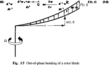
We begin with a closer examination of the hingeless rotor. Figure 3.5 illustrates the out-of-plane bending, or flapping, of a typical rotating blade cantilevered to the rotor
 |
|
hub. Using the commonly accepted engineer’s bending theory, the linearized equation of motion for the out-of-plane deflexion w(r, t) takes the form of a partial differential equation in space radius r and time t, and can be written (Ref. 3.5) as
where EI(r) and m(r) are the blade radial stiffness and mass distribution functions and Q is the rotorspeed. The function F (r, t) represents the radial distribution of the time – varying aerodynamic load, assumed here to act normal to the plane of rotation. As in the case of a non-rotating beam, the solution to eqn 3.8 can be written in separated variable form, as the summed product of mode shapes Sn(r) and generalized coordinates Pn(t), i. e.,
where P1 is given by eqn 3.10 with n = 1. Equations 3.10 and 3.16 provide the solution for the first mode of flapping response of a rotor blade. How well this will approximate the complete solution for the blade response depends on the form of the aerodynamic load F(r, t). From eqns 3.10 and 3.12, if the loading can be approximated by a distribution with the same shape as S1, then the first mode response would suffice. Clearly this is not generally the case, but the higher mode responses can be expected to be less and less significant. It will be shown that the first mode frequency is always close to one-per-rev, and combined with the predominant forcing at one-per-rev the first flap mode generally does approximate the zero and one-per-rev blade dynamics and hub moments reasonably well, for the frequency range of interest in flight dynamics. The approximate model used in the Helisim formulation simplifies the first mode formulation even further to accommodate teetering and articulated rotors as well. The articulation and elasticity is assumed to be concentrated in a hinged spring at the centre of rotation (Fig. 3.6), otherwise the blade is straight and rigid; thus
r
Fig. 3.6 The centre-spring equivalent rotor analogue
Such a shape, although not orthogonal to the elastic modes, does satisfy eqn 3.11 in a distributional sense. The centre-spring model is used below to represent all classes of retention system and contrasts with the offset-hinge and spring model used in a number of other studies. In the offset-hinge model, the hinge offset is largely determined from the natural frequency whereas in the centre-spring model, the stiffness is provided by the hinge spring. In many ways the models are equivalent, but they differ in some important features. It will be helpful to derive some of the characteristics of blade flapping before we compare the effectiveness of the different formulations. Further discussion is therefore deferred until later in this section.


